
LV Automatic Transfer Schemes
In modern electrical power systems, ensuring a reliable and continuous supply of electricity is critical, particularly in facilities where downtime can result in significant operational disruptions and financial losses. Low voltage automatic transfer schemes at substations play a vital role in maintaining this continuity by seamlessly switching between different power sources in the event of a fault or power outage.
 ATS Schematics and Logic Analysis for a Substation 415V AC Auxiliary Supply Panel
This article delves into the intricacies of low voltage automatic transfer schemes at substations. We will explore the design and implementation of these systems, providing detailed insights into various ATS components and their functions.
Within this framework, the Low Voltage Bus Coupler acts as a bridge, facilitating the synchronization and transfer of power between different busbars. Interlocking mechanisms further enhance the safety and reliability of these systems, ensuring that operations proceed smoothly without the risk of power conflicts or overloads.
Interlocking mechanisms within the low voltage substation auto transfer scheme are scrutinized, emphasizing their importance in preventing conflicting operations and ensuring safe and efficient switching. The operations of auto transformer schemes, including automatic, manual, and off operation selections, are thoroughly discussed to provide a comprehensive understanding of their practical applications.
By the end of this article, readers will have a clear grasp of the operational principles, design considerations, and practical implementation strategies for low voltage automatic transfer schemes at substations.
Whether you are a seasoned professional or new to the field, this article offers valuable knowledge to enhance your understanding and application of these critical systems in electrical power distribution.
- Low Voltage Automatics Transfer Scheme at the Substations
- AC Supply Single Line Diagram
- Auxiliary Transformer Supply Incoming Panel
- 250kVA Diesel Generator Supply Incoming Panel
- Low Voltage Bus Coupler
- Interlocking at the Low Voltage Substation Auto Transfer Scheme:
- Auto Transformer Scheme Operations:
- BONUS (PDF) 🔗 Download Complete Schematic Diagram of 415V AC Auxiliary Supply Panel
1. Low Voltage Automatics Transfer Scheme at the Substations
Substations are equipped with low voltage power supplies, often referred to as auxiliary supplies, which are provided by auxiliary transformers. There may be one or more auxiliary transformers within a substation. Given the critical nature of substation operations, redundancy is essential to ensure a backup option if the auxiliary supply fails.
One approach to achieve redundancy is by installing two auxiliary transformers. In the event of a failure of one transformer, the other can continue to supply power. These auxiliary transformers receive their power from distribution transformers, which are, in turn, powered by the main power transformer.
For instance, in a 132/11kV substation, the voltage is stepped down from 132kV to 11kV by the power transformer and then from 11kV to 400V by the distribution transformer.
Therefore, simply having two auxiliary transformers does not provide sufficient redundancy. To address this, a backup 250kVA generator is utilized. This generator ensures that if the 132kV line fails, or if there is a failure or maintenance of the auxiliary transformer, the substation can still be powered.
Figure 1 – 132 kV substation single line diagram

2. AC Supply Panel Single Line Diagram
In this example, the substation employs a single AC low voltage feeder scheme. It is a 132kV substation with one auxiliary transformer fed by a 132kV transmission line. This line is connected to a 132/11kV transformer, which steps the voltage down to 11kV, and then further steps it down to low voltage (LV) using an 11/0.4kV distribution transformer.
If the 132kV line trips, the substation’s supply is interrupted.
To mitigate this risk, a backup generator is provided. The substation contains two LV buses with a coupler between them, as illustrated in Figure 2, which shows the single line diagram of the AC incoming panel.
Essential loads include emergency lighting, DC battery charger supply, fire-fighting systems, fire alarm system supply, and other critical equipment. Additionally, the generator cannot operate in parallel with the national grid supply because no synchronization facility is provided.
Therefore, an interlocking arrangement is included at the panel to ensure safe operation.
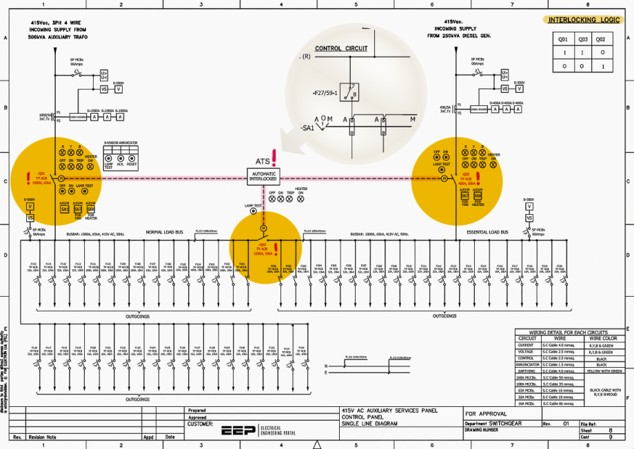
Figure 2 – The Single Line Diagram of the Substation Auxiliary Supply Panel (click to zoom)
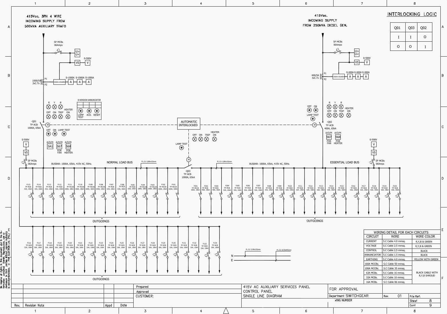
3. Auxiliary Transformer Supply Incoming Panel
Refer to Figure 2, which shows the low voltage (LV) incoming feeder emanating from the LV side of an 11/0.4 kV transformer. The LV side of the transformer is connected in a star configuration with a four-wire system, including a neutral connection. The auxiliary transformer, also known as the station service transformer, is connected to the normal busbar.
On the cable side, an under and over-voltage relay is fitted. In case of voltage fluctuations beyond the limit, the incoming circuit breaker (ACB) trips with a suitable time delay. The under or over-voltage relay also senses the absence of voltage and ultimately trips the incoming breaker Q01.
This means the scheme automatically isolates the auxiliary supply from the busbar if the grid voltage supply fails.
Next, a current transformer (CT) with a ratio of 100/5 A is connected. This is a three-phase current transformer, and the polarity markings of the CT can also be seen. Here, P1 is at the cable side and P2 is at the busbar side. The CT’s secondary wiring is further connected to the energy meter, VAR meter, and ammeters.
Figure 3 – Wiring Diagram of the Substation Auxiliary Supply Panel (click to zoom)

Three-phase indication lamps are provided, indicating RED, YELLOW, and BLUE phases. The Q01 is the air circuit breaker (ACB) with a rating of 1000 A continuous current and 65 kA short-time rating. The “M” indicates that the ACB is motor-operated. The circuit breaker is connected to the LV busbar, which has several feeders connected to it.
Related electrical guides & articles


Muhammad Kashif
Muhammad Kashif Shamshad is an Electrical Engineer and has more than 17 years of experience in operation & maintenance, erection, testing project management, consultancy, supervision, and commissioning of Power Plant, GIS, and AIS high voltage substations ranging up to 500 kV HVAC & ±660kV HVDC more than ten years experience is with Siemens Saudi Arabia.Profile: Muhammad Kashif
