Prefabricated Substation FAT
This technical article will go over various aspects of factory acceptance testing (FAT) for custom prefabricated power substation and its related electrical components (such as MV and LV switchgear, MV-LV Motor Control Centre (MCC), UPS systems, AC/DC auxuliary power supply panels, and so on) to ensure that the systems were properly manufactured in full compliance with design specifications.

 Checks for Successful Substation Factory Acceptance Testing
We will look at the different stages of the project life cycle to address the protocols and safety measures necessary for a successful factory acceptance test (FAT).
The testing aims to verify that the equipment and systems function properly and comply with the manufacturers’ specifications and relevant standards. This work entails multiple risks. The user bears the responsibility for safety. An examination of regulatory constraints is necessary before conducting tests.
It’s worth mentioning that there are no standard FAT or SAT work instruction documents. Both testers and commissioners have variations of their testing and commissioning documents.
To summarize, Factory Acceptance Testing are conducted to ensure compliance with specific specifications, resulting in high-quality products. The tests are typically conducted with the customer and, in more rigorous circumstances, with a third-party inspection agency.
All potential problems, deviations, and requests are duly recorded.
This technical article will underscore the significance of a comprehensive and organized Factory Acceptance Test (FAT) for a successful substation startup and operation.
- Prefabricated Power Substation:
- FAT Agenda:
- Bid Clarification Process
- Kick Off Meeting:
- Safety Precautions During Electrical Inspection:
- Equipment Internal Inspection:
- Final Inspection and Equipment Testing:
- Other Substation Equipment Tests:
- Attachment (PDF) 🔗 Download ‘Analysis Handbook for Power Systems Using MATLAB and ETAP’
1. Prefabricated Electrical Substation
1.1 What is a Prefabricated Power Substation?
A prefabricated power substation is a substation that has been specially engineered, prefabricated, and completely integrated to satisfy the exact requirements of the electrical system package while reducing expediting and on-site civil construction costs. And that’s it, as simple as that.
It primarily comprises transformers, associated switchgear, and control panels, all contained within a protective enclosure. It can facilitate secure and effective electricity delivery.
Manufactured in a controlled environment, these prefabricated substations are constructed in compliance with standards and safety rules.
1.2 Equipment Inside the Substation Building
- Low-voltage and Medium-voltage Switchgear,
- Motor Control Centers (MCC),
- Oher Associated Electrical & Control Equipment (i.e. VFD, UPS, Batteries, Instrumentation, etc.)
- HVACs
- Equipment for Fire & Gas Detection / Suppression
- MV/LV Switchgear
- MV/LV MCC
- UPS Systems
- Battery Chargers
- SS automation
Figure 1 – Package & Containerised Substation

2. FAT Agenda
DAY #1
1. Bid Clarification
- Review Request for Quote (RFQ) package and all commercial/technical documents
- Initiate estimating process & provide quote for the project
2. Kick Off Meeting
- Define project members and their roles.
- Project clarification and review documentation.
3. Safety Precautions During Electrical Inspection
- General precautions/checks that needs to be observed/made before & during testing of electrical equipment.
- Understanding the manufacturing facility & equipment under test.
4. Equipment Internal Inspection
- Getting equipment ready for the inspection.
- Check equipment against all checklist and start with in-process inspection.
- Start final inspection by performing various tests on the equipment (such as bussing check, control check, primary injection test etc.)
- Make sure equipment is ready for the factory acceptance test.
Figure 2 – Visual inspection check of a medium voltage switchgear

DAY #2
1. Bid Clarification
- Define project scope, schedule and timeframe for each phase of project.
2. Pre-FAT Meeting
- Review inspection test plan (ITP) for each equipment type.
- Define roles of each team member who is going to perform/witness the test.
- Set an agenda illustrating the FAT schedule.
3. FAT Process (Test-Punch list-Retest)
- Functional Check of:
- MV/LV MCC
- MV/LV Switchgear
- Annunciators
- Fire Alarms
- HVAC
- Plant interlock scheme
- Temporary power panel
- Ship prep after FAT
Watch Lesson – Insights into Commissioning & Troubleshooting
3. Bid Clarification Process
The bid clarification process begins when a project issues a Request for Quotation (RFQ) which includes technical and commercial requirements.
- The technical information includes the details specifying the equipment details and fabrication specifications.
- The Sales Engineer/Estimating Engineer performs a detailed review of the project specifications/drawings and creates a costed bill of material and preliminary layout, which meets the requirements of the RFQ.
- Any exceptions to the technical specifications are identified and documented by the person estimating the job.
The preliminary design includes:
- Outline dimensional information for Pre-fab building/Equipment sizing.
- Estimated material & labor costs based on project’s spec interpretation.
- Preliminary Bills of Material (BOM’s) including Pre-fab building, buyout items, Switchgear, MCC’s, Bus Duct, breakers and devices as per the project specifications.
4. Kick Off Meeting
Kick-off meetings are invaluable to disseminating information within the project environment. It is extremely important that correct and accurate information is processed and transferred from project to engineers.
This is the opportunity for vendor to ensure that their interpretations are per project requirement and also an opportunity for customer to understand what they are really getting from the vendor.
Figure 3 – Kick Off Meeting Example

4.1 Project Clarification
- Ensure that all technical discrepancies and questions have been addressed prior to starting the design process.
- Lesson learned from the past projects.
- Discuss any unique fabricated or buyout items, alignment of vendor deviations or exceptions from the project requirements, or any long lead time items.
4.2 Define Project Members and Their Roles
- Review project organization chart and associated roles.
- Discuss the tasks of different vendors associated with the project and the associated deliverables expected to be produced.
Each project participant should know their responsibility and understand the issues that may impact the successful completion of the project.
4.3 Project Organization Chart
Figure 4 – Substation FAT organization chart

4.4 Technical Specification
Figure 5 – Substation technical specification

4.5 Review QA/QC Procedures & Forms
Quality Assurance / Quality Control (QA/QC)
- Discuss test description, method of test and responsible party for each equipment type.
- Define customer inspection policy and specify if additional tests are required.
4.6 Capture Meeting Minutes
It’s important to document major discussion points, resolutions, action items and the corresponding team member responsible for those actions.
Useful Study – Technical Documentation for a Turnkey Substation
5. Safety Precautions During Electrical Inspection
5.1 PPE for Electrical Inspection
- Safety Glasses: to be used when circuit bridging (jumpering)
- Touchless AC voltage indicator: to detect the presence of AC voltage
- Lock out device: for electrical lockout/tagout
- Hasp: for electrical lockout/tagout
- Personal lock & tag: for electrical lockout/tagout
5.2 General Safety Precautions and Checks
- Do not wear conducive article of jewelry and clothing.
Figure 6 – Do not wear conducive article of jewelry and clothing

- Always use test equipment that is in good working order and in safe condition.
- Always assume all conductors are “HOT” until verified to be de-energized.
- A ground wire must be attached to all equipment under test and to all test equipment prior to energizing.
- Get acquainted with the equipment to be tested prior to energization.
- When using wall or floor junction boxes, the power cable should be secured to the box to prevent the cable from being unplugged.
- Arrange power cords or other types of extension cords such that it prevents a trip hazard.
- Always turn off test equipment and disconnect from the source before disconnecting it from the job.
- PT and CPT primary circuit fuses MUST be removed when running secondary voltage unless the primary is energized with bus wires removed from the fuse block.
- Power factor correction capacitors and surge arrestor should not be energized.
- Never use alligator clips to attach high voltage test carts leads to the bus bar.
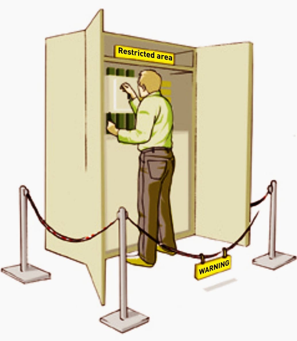
- Define the boundaries that prohibit unauthorized personnel from entering the restricted area.
Figure 7 – Boundaries that prohibit unauthorized personnel from entering the restricted area
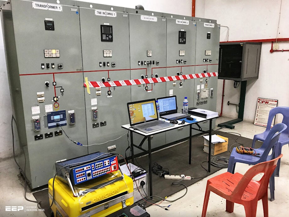
- Use warning lights on the test equipment to warn area personnel of presence of voltage on the equipment.
Figure 8 – Warning lights on the test equipment during the FAT

- Limit the use of high voltage as much as possible. Ensure that all high voltage test leads are color coded and readily identifiable. “A” phase is black, “B” phase is red and “C” phase is yellow.
Related electrical guides & articles


Edvard Csanyi
Hi, I'm an electrical engineer, programmer and founder of EEP - Electrical Engineering Portal. I worked twelve years at Schneider Electric in the position of technical support for low- and medium-voltage projects and the design of busbar trunking systems.I'm highly specialized in the design of LV/MV switchgear and low-voltage, high-power busbar trunking (<6300A) in substations, commercial buildings and industry facilities. I'm also a professional in AutoCAD programming.
Profile: Edvard Csanyi