
Tripping, Closing & Blocking Coils
This technical article embarks on a comprehensive exploration of various facets of circuit breaker technology, traversing from the fundamental principles of solenoid coils to the sophisticated mechanisms of SF6 density monitoring circuits. Delving into the intricacies of circuit breaker tripping and closing coil arrangements.
 Circuit breaker schematics in a nutshell: Tripping, closing and blocking coil arrangements
Furthermore, the discussion extends to the critical role played by circuit breaker blocking coils, offering a shield against inadvertent operations and enhancing system safety.
As the narrative progresses, the focus shifts towards the sophisticated realm of SF6 density monitoring circuits, unraveling the mechanisms behind warning and alarm systems, as well as interlock mechanisms crucial for preventing incorrect switching operations. The article navigates through the nuanced concepts of forced trip and maintain current position, shedding light on their implications for circuit breaker operation in diverse scenarios.
Venturing deeper, readers will be introduced to the intricacies of gas-insulated circuit breakers, particularly at the formidable 132kV level, exploring the schematics of SF6 lockout mechanisms and grappling with the concept of slamming in control circuits.
Finally, the narrative concludes by unraveling the operational flexibility offered by local and remote selection switches, elucidating their significance as safety features that empower operators with precise control over circuit breaker operations.
- Solenoid Coil: The Heart Of a Circuit Breaker
- Circuit Breaker Spring Charge Mechanism
- Circuit Breaker Tripping and Closing Coil Arrangements
- Circuit Breaker Blocking Coil
- SF6 Density Monitor Circuit in Circuit Breakers:
- 132kV Gas Insulated Circuit Breaker SF6 Lockout Schematics
- What is slamming the circuit breaker control circuit
- Closing Coil of Circuit Breaker
- Tripping or Opening Coil of Circuit Breaker
- Auxiliary Contacts of Circuit Breaker:
- Local / Remote Selection Switch:
- BONUS 🔗 Download 132kV GIS Drawings of HV Devices and LCC (PDF, 11.8Mb)
1. Solenoid Coil: The Heart Of a Circuit Breaker
A solenoid coil is a fundamental electrical component employed in various applications, characterized by a wire wound tightly around a core, typically composed of metal. This winding configuration is designed to generate an electromagnetic field when an electrical current flows through the coil.
Upon energization, the electrical current induces the generation of a magnetic field around the coil. This magnetic field interacts with the core material, resulting in the production of a force known as electromagnetic force.
Essentially, the electromagnetic field created by the energized coil serves as a source of energy, capable of exerting a pushing or pulling force on nearby objects or components. This principle of electromagnetic induction enables solenoid coils to perform a wide range of functions, including actuating valves, controlling mechanical devices, and triggering switches in various electrical and electromechanical systems.
Figure 1 – The Solenoid Coil’s Working Mechanism

The solenoid depicted in Figure 2 illustrates a push-type configuration commonly used in circuit breakers. These solenoid coils are characterized by their short-duty nature, meaning they require brief energization periods.
Prolonged pulses or commands could lead to overheating and eventual damage to these coils.
Figure 2 – Picture of the solenoid (Tripping coil) used in the circuit breaker

Upon energization of the closing coil in the circuit breaker, the plunger within the solenoid experiences the influence of the electric field, prompting linear motion. As the plunger advances forward, it contacts the latch mechanism, as depicted in Case “a” and “b” of Figure 3, indicating that the circuit breaker is in the closed position.
Notably, the circuit breaker comprises one main contact and two normally open auxiliary contacts.
As the plunger continues its forward motion, it eventually strikes the latch, causing it to open, as illustrated in Case “c”. Subsequently, the pole of the circuit breaker begins to open, as depicted in Case “d”, eventually reaching a fully opened position in Case “e”.
Moreover, the auxiliary contact of the circuit breaker also opens, discontinuing the supply to the coil. This normally open contact serves a dual purpose: firstly, it acts as a safety measure by cutting off the continuous supply to the coil, thus preventing potential damage.
Secondly, it prevents re-energization of the tripping coil and avoids repeated impacts of the plunger against the latch when the circuit breaker is already in the open position.
Figure 3 – Spring operated circuit breaker operations

2. Circuit Breaker Spring Charge Mechanism
When the circuit breaker spring is charged, it accumulates potential energy, which is then held in place by a latch mechanism. Upon activation of the solenoid coil, the plunger strikes the latch, releasing the spring’s stored energy. This release of energy causes the circuit breaker to either open or close, depending on the specific operation required.
It’s important to note that circuit breakers typically feature two springs: one for closing the circuit breaker and simultaneously charging the tripping spring, and another for opening the circuit breaker.
Additionally, the opening spring is charged by the closing spring. As the closing spring is released to close the circuit breaker, it also compresses the opening spring, thereby storing energy for the subsequent opening operation.
Suggested Video – Spring Charge Indication
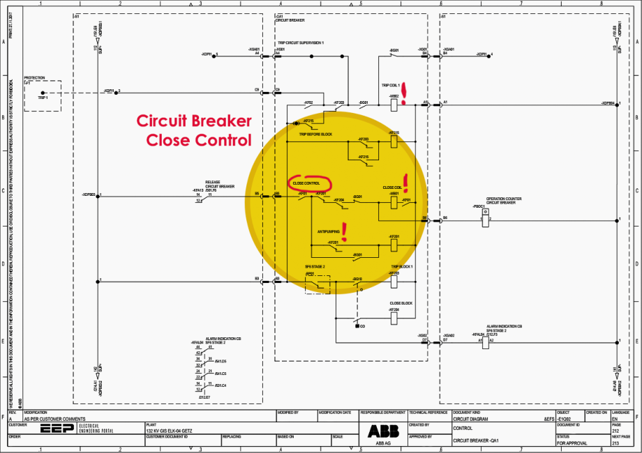
3. Circuit Breaker Tripping and Closing Coil Arrangements
In a substation, the circuit breaker is equipped with one closing coil and two tripping coils, highlighting the critical importance of the tripping function. Redundancy is paramount in the tripping circuit to ensure reliability in fault scenarios. Given the pivotal role of tripping in disconnecting faulty circuits swiftly, redundancy is achieved by having two tripping coils. If one coil encounters a failure, the other serves as a backup, ensuring the breaker can still trip effectively.
Furthermore, to guarantee continuous operation, each tripping coil is connected to a separate DC system or battery backup. Substations typically maintain two battery banks, each dedicated to powering a distinct tripping circuit.
Related electrical guides & articles


Muhammad Kashif
Muhammad Kashif Shamshad is an Electrical Engineer and has more than 17 years of experience in operation & maintenance, erection, testing project management, consultancy, supervision, and commissioning of Power Plant, GIS, and AIS high voltage substations ranging up to 500 kV HVAC & ±660kV HVDC more than ten years experience is with Siemens Saudi Arabia.Profile: Muhammad Kashif
