
Optimizing the specification
The majority of utilities are normally extremely well aware of the economic aspects and savings that can be obtained at all stages of the transformer’s life cycle. This is because the purchase of a transformer involves a very high capital outlay. In most cases, the department responsible for system planning will be the one to decide the required number and size of transformers.
 11 factors that significantly influence the transformer price (Be careful when specifying)
They will then make a request to the transformer specialists to develop the purchase and technical specification, which, in this particular instance, will be based only on the user’s expertise and experience.
Because of this, it is possible that the specification is not completely optimized to meet the requirements of the individual service. As a result, it is strongly recommended to involve the supplier at this early stage in order to take full advantage of the manufacturing knowledge and experience that the supplier possesses. This will result in a specification that will cover the requirements for a fully optimized transformer from both the perspective of the manufacturer and that of the user.
The following is a list of potential factors that can have an effect on those aspects:
- Winding configurations, such as Yy against Yyd or Dy or Yd, etc.
- Tertiary stabilizing winding for star/star transformers
- On-load tap changers (OLTC) and De-energized tap changer (DETC):
- Transformer Life Expectancy, Capacity, Capitalization of Losses and Overloading:
- Test requirements, special transformer tests (FRA, SC, no-load current harmonics, LV impedance measurement, etc.)
- Environmental conditions such as sound level, oil type, etc.
- Insulation coordination and insulation level of power transformer
- On-line Monitoring, if needed on new transformer units
- Factory and Design review, Short-circuit performances
- Auxiliary equipment, such as such as bushings, CT’s, tap-changers, etc.
- Unification of transformers
- BONUS! Transformer Handbook (PDF)
Let’s discuss each of the above factors.
1. Winding configurations
Such as Yy against Yyd or Dy or Yd, etc.
When it comes to manufacturing and running the business, the winding configuration of the transformer has a fairly significant impact on the economic factors involved. Depending on the arrangement, it may be possible to cut the costs of material and labor while maintaining the same or even better operating conditions, and even while achieving higher levels of reliability.
In most cases, the use of a star (Y) winding with less insulation at the neutral end will result in lower costs than the use of a fully insulated delta winding (D) for the high voltage, particularly when a tap-changer is involved.
Autotransformers have a lower overall MVA cost than fully double wound transformers, but they electrically bind the two systems together, meaning they cannot have independent earthing. This is because autotransformers do not have fully double wound coils.
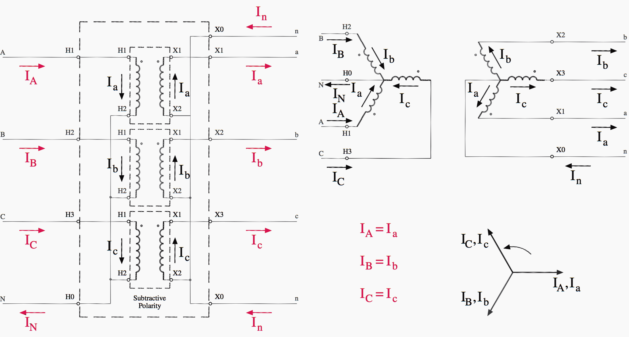
The wye–wye connection is depicted in Figure 1, either as a single three-phase unit or as three single-phase transformers. There are depictions of the polarity dots as well as the bushing labels.
Figure 1 – Wye–Wye Transformer Connections Diagram (click to expand diagram)
2. Tertiary stabilizing winding for star/star transformers
About seven to eight percent of the total cost of the transformer is added on due to the addition of a tertiary delta stabilizing winding (connection Yyd). Transformers with stabilizing winding have a zero-sequence impedance of 10–20 percent, whereas star/star transformers without stabilizing winding have a zero-sequence impedance that ranges from 50–80 percent.
If a provision is provided to open the delta circuit by removing two bushings from the transformer in the event that it is not required, a tertiary stabilizing winding is not typically a detriment for a transformer, with the exception of the cost associated with installing it.
This is not the case for tertiary windings that have been brought out and loaded, as these windings have the potential to experience a three-phase short-circuit on the tertiary side. Under certain circumstances, the deficiency caused by the absence of tertiary windings can be compensated for by employing one of several alternative internal technical solutions.
Figure 2 – Star-star connection with tertiary winding
3. On-load tap changers (OLTC) & De-energized tap changer (DETC)
In general, a delta winding on the HV side is more expensive than a star winding, particularly when a tap-changer is necessary. This is especially true when the cost of the tap-changer is taken into consideration. When an OLTC or DETC is necessary, the cost of the transformer can be decreased by positioning it on the HV side of the distribution system, depending on the parameters of the service.
When viewed from an operational standpoint, this normally does not have an effect on the transformer’s abilities to perform its function.
The OLTC/DETC is capable of covering the whole spectrum of regulation, which includes the variation of voltage on both the LV and HV sides. An OLTC or DETC that can switch at a lower current has a higher switching reliability and requires less maintenance.
Transformers in substations always require OLTCs, although DETCs are increasingly being specified for step-up transformers (unit generator transformers) in generating stations. OLTCs are required in all cases for substation transformers.(OLTCs are still only specified in a select number of nations)
DETCs are either not used at all or only used very infrequently, and after being used at the same tap location for a number of years, they could become a source of difficulties.
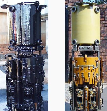
Figure 3 – Transformer on-line tap-changer gear before and after maintenance
4. Life Expectancy, Capacity, Capitalization of Losses and Overloading
In most cases, the planning department of a utility will be the one to establish the capacity of the transformers that are necessary. Transformer managers often do not have much of a say in this area. In most cases, the group responsible for planning the maintenance will have taken into account the existing and future loads, as well as the potential for overloading and emergency loading.
Nevertheless, one area in which the transformer manager might have some input is the inter-changeability of the transformer in the event that another transformer fails somewhere else. It is obvious that the capacity of the transformer is just one of the factors that will determine how it could be reused in the system if it were to become necessary at some point in the future.
The lifespan of a transformer, which is distinct from the lifespan of the insulating system, is not currently defined by any of the standards that are in place. The opinion of the accountant has been accepted as the standard on the life expectancy of a transformer, which is around 25–35 years when it is operated under typical load and service conditions.
There are a variety of up-to-date methods of calculation that can be used to determine the impact of overloading.
Worth Reading – Field secrets & warnings in transformer mechanical check & visual inspection
Field secrets and warnings in power transformer mechanical check and visual inspection
On the other hand, years of practical experience have proven that lower loads can often extend the lifespan of transformers to 40, 50, or even more years. This can result in a life expectancy that is approximately sixty percent longer. It is just as valid, if not more so, to base evaluations on the longer life expectancy, and using this factor can have a considerable impact on how the competing transformer bids are valued.
This fact has the potential to be linked with the cost of losses as well as the anticipated state of the transformers’ ability to perform.
It should be brought to everyone’s attention that a higher cost of losing results in a higher cost of purchase. As a result, one ought to take this into consideration, particularly in circumstances in which the transformer’s loading demonstrates a significant variation in accordance with the seasons and the time of day. In light of these considerations, a more affordable option is warranted.
On the other hand, the manager of the transformer, who is accountable not only for current maintenance but also for the cost of losses in a system (which includes the transformer), may insist on placing a greater figure on the cost of losses in the bid.
Overloading is not only feasible but also acceptable, and it is accounted for in accordance with a variety of standard standards. Whenever the operating condition calls for a distinct overloading capacity, it ought to be defined and expressed in a clear manner. Because of the necessity for it to be developed as a specialized unit, the costs are affected when the overloading capacity is increased.
At the time of purchase, these costs are supposed to be weighed against the purchase of a unit with a higher standard rating or the specification of a transformer with a higher overloading capacity than is strictly required.
The following formula can be used to make a rough estimate of the increase in mass of active materials (magnetic steel, copper, oil, and so on) that occurs with increasing rated power of the transformer:

in which:
- m stands for a mass,
- S stands for a rated power,
- Subscripts “1” and “2” stand for transformer 1 and 2.
For instance, if the rated power of the transformer rises by sixty percent (for instance, from one hundred to one hundred and sixty MVA), then the amount of active material will rise by forty-two percent. This rate of growth applies equally well to both the load and no-load losses. Nevertheless, particularly in the case of network transformers, the cost of the transformer does not rely linearly upon the mass.
This is due to the expense associated with purchasing an on-load tap changer, bushing, and many auxiliary components. In the given scenario, the cost ought to go up by somewhere in the range of 23-30%.
In general, the price of a transformer (PR) rises with an exponent of approximately 0.5 – 0.6 on the relation of the transformer’s primary power to its secondary power:

Recommended Study – A study of lifetime management of generator step-up power transformers
A study of lifetime management of generator step-up power transformers
5. Test specification and factory test
During standardization, it might be possible that the design and routine tests required by existing standards are not enough to prove that the specified requirements are fulfilled. In this case, the specification should include some “special tests”.
The below list includes type tests, routine tests, as well as additional and special tests, which should be taken in consideration. Special requirements on the loading ability shall be proved by other special tests in an agreement between the purchaser and the manufacturer.
For example, the use of DGA as a tool to detect weak characteristics in design and manufacture should especially be taken into consideration.
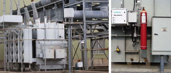
Figure 4 – Siemens’s TMDS™ Smart Monitor turns transformer monitoring
5.1 Routine tests
- Measurement of winding resistance
- Measurement of voltage ratio and verification of vector group phase displacements
- Measurement of short circuit impedance and load loss
- Measurement of no-load loss and current
- Induced overvoltage and applied power frequency voltage
- Partial discharge measurements in combination with the induced overvoltage test
- Lightning and switching surge voltage
- On-load tap changers
- Measurement of insulation resistances to earth and between windings
- Oil diagnostic gas analysis (DGA)
- SF, bushing flange isolation
- Magnetic circuit and associated insulations
5.2 Type tests
- Load loss and impedance measurements over tapping range
- Temperature rise
- Lightning and switching surge voltage (if not a routine test)
- Sound power levels
- Zero phase sequence impedances
- Measurement of fan and oil pump power consumption
- Tank vacuum test
- Tank overpressure test
5.3 Special tests
- Recurrent surge oscillograph (RSO) measurements
- Measurement of capacitances: from windings to earth and between windings
- Determination of transient voltage transfer characteristics
- Short circuit withstand test
- Measurement of no-load current harmonics
- Low voltage impedance measurement
- Load current and overload capabilities
- Frequency response analysis (FRA)
- Thermographic survey (tar* temperature survey)
5.4 Additional tests
- Checks on correspondence relating to the approval of drawings
- Verification of accessory performance and operation
- Corrosion protection
- No-load current at low voltage (mains voltage)
- Determination of core temperature rise
- Verification of oil quality
- Inrush current test (site test)
Recommended Guide – Guidelines to power transformer type, routine and special tests
Guidelines to power transformer type, routine and special tests
6. Environmental conditions (noise, oil type)
The utilization of “re-used” or “equivalent to new” oil is a topic of discussion in many nations due to the economic benefits it provides. When defining new transformers, the usage of such oil should be given significant weight as a potential option. It is expected that the performance of this kind of oil will be at least comparable to that of modern oils. The accelerated aging tests need a disproportionate amount of focus and concentration.
Nonetheless, increasing the frequency of oil maintenance in order to evaluate the oil’s quality will result in additional costs; nonetheless, these costs are typically negligible in comparison to the initial investment required for the equipment.
The decibel levels that power transformers are allowed to emit are becoming an increasingly important regulatory consideration in many nations.
There are noise generators in both the core and the windings of the transformer. There are several standards that do not tie the necessary noise level in the specification to both sources’ noise levels. The most recent designs have introduced a phenomenon in which the level of noise created by the current flowing through the windings can produce a volume that is audibly louder than the noise caused by the flux flowing through the core.
The noise restrictions that are required should be defined in greater detail in the specification. Only in exceptional circumstances, such as when the needed noise limit is extremely low, can one think about erecting external barriers to lower the noise level.
In Figure 5, it can be seen that the waveform of measured impulsive noise for the 230, 315 and 735 kV with the power spectrum of the impulses.
Note that the measured impulsive noise is similar in the three areas of voltage in terms of impulses generation.
Figure 5 – Impulsive noise measurements in substation 1 for 735 kV (a), 315 kV (b) and 230 kV (c) areas; Time domain (top) and power spectrum of all the impulses (bottom)

7. Insulation coordination and insulation level of power transformer
When constructing the insulation system of a power transformer, it is important to take into account all of the stresses that will be placed on the equipment. Lightning impulse (LI), switching impulse (SI), applied voltage, induced voltage with PD measurements, transients, and service voltage are the stressors in question here. In order to coordinate the insulation system so that it can bear the maximum stresses, the worst-case scenario in each location of the insulation is taken into consideration.
Alterations to the LI withstand will not inevitably result in a reduced insulation system, and as a consequence, the price of the transformer might not be impacted either.
The transformer insulation levels and the insulation test to be applied according to IEC 60076-3 is shown in the below table.
Table 1 – Transformer insulation levels and the insulation test to be applied
| Winding structure | Maximum operating voltage Um kV | Tests | ||||
| Lightning impulse (LI) | Switching impulse (SI) | Long duration AC (ACLD) | Short duration AC (ACSD) | Applied voltage test | ||
| Uniform insulated | Um ≤ 72,5 | type (note 1) | na | na (note 1) | routine | routine |
| Uniform and Uradually insulated | 72,5 < Um ≤ 170 | routine | na | special | routine | routine |
| 170 < Um ≤ 300 | routine | routine (note 2) | routine | special (note 2) | routine | |
| ≥ 300 | routine | routine | routine | special | routine | |
| Note 1: In some countries, in transformers with Um ≤ 72,5 kV applied as routine test and the ACLD test is applied as routine or type test. Note 2 : If the ACSD test is defined, the SI test is not applied. | ||||||
8. Maintenance and On-Line Monitoring
Only the strategic units will have on-line monitoring implemented on new units for consideration. In any event, plans for the possible installation of sensors in the near future must to be taken into consideration. A significant portion of a transformer’s useful lifespan, as well as its dependability and availability, can be attributed to the level of care that the device receives. The minimum required maintenance is typically outlined in the instruction manuals provided by the manufacturer.
However, users of transformers should have maintenance strategies that take into account a variety of parameters, including the significance of the unit, the expenses associated with downtime, the costs of maintenance, and so on.
Figure 6 – Checking transformer fans and radiators during the maintenance program

9. Factory and Design review, Short-circuit performances
Review of the factory and the design are essential steps in determining whether or not all parties have a common knowledge of the specifications’ requirements and capabilities. It’s as simple as that! It is essential to emphasize that the short circuit withstand capability is dependent not only on the appropriate design, but also, to a large extent, on how well the manufacturing processes are regulated.
This is because of the close connection between the two factors.
Figure 7 – An example of a power transformer drawing (click to zoom)

10. Auxiliary Equipment
The specification stipulates that auxiliary equipment, such as bushings, CT’s, tap-changers, and the like, must have the overloading capacity to meet its requirements. The active component of the transformer typically has a significantly longer lifespan than the auxiliary equipment, which typically has a much shorter lifespan.
In addition to this, it necessitates a great deal more care (and hence, expense) than the active component.
This additional expenditure is easily manageable as a fraction of the average annual maintenance cost.
Further Study – Often incorrectly specified and ordered: Power transformer fittings and accessories
Often incorrectly specified and ordered: Power transformer fittings and accessories
11. Unification of transformers
It is advised that the specifications be standardized as much as possible in order to realize the most cost-effective device possible. This standardizes the sizes of the transformers as well as their ratings and impedances.
BONUS! Transformer Handbook (PDF)
Download Transformer Handbook in PDF format (for premium members only):
Sources:
- Economics Of Transformer Management by Cigre Working Group A2.20
- Customers Specifications For Transformers 100 Mva And 123 Kv And Above by Cigre Working Group 12.15
- Conducting Design Reviews For Transformers 100 Mva And 123 Kv And Above by Cigre Working Group 12.22
Related electrical guides & articles


Edvard Csanyi
Hi, I'm an electrical engineer, programmer and founder of EEP - Electrical Engineering Portal. I worked twelve years at Schneider Electric in the position of technical support for low- and medium-voltage projects and the design of busbar trunking systems.I'm highly specialized in the design of LV/MV switchgear and low-voltage, high-power busbar trunking (<6300A) in substations, commercial buildings and industry facilities. I'm also a professional in AutoCAD programming.
Profile: Edvard Csanyi
