
Craftsmanship in Electrical Installations
This technical article deals with the practical aspects of commercial and industrial electrical installation work. It is of the utmost importance that the practical task be done in the appropriate manner. Electrical installations in commercial and industrial settings are often complete and intricate systems.
 Seven golden foundations of good electrical installation work
When these systems are implemented in newly constructed or recently renovated buildings, a variety of approaches are utilized in the process of distributing and routing electrical circuits.
There are a many different manufacturers who are capable of supplying the entire spectrum of necessary equipment. This includes a selection of different types of trunking and conduit, cable trays, cable ladders, and other items like power poles or posts, all of which allow the electrical installer to present a full and comprehensive installation.
There are various criteria and rules that have a general application, and these apply to any wiring system that may be utilized. Before moving on to an in-depth discussion of the several foundations of good electrical installation work, these will be briefly discussed. It is required that “Good craftsmanship and proper materials must be used,” as stated in IEE regulation 134.1.1 .
It is imperative that you never forget the selection of materials, the organization of the job, as well as your level of expertise and experience, all work together to determine the nature and effectiveness of the installation.
- Proper Electrical Tools
- Wise Selection of Cable Runs
- Preventing the Spread of Fire
- Identification of Conduits and Cables
- Cables in Low-Temperature Areas
- Single-Core Cables
- Bunching of Outgoing and Incoming Cables
- BONUS! A Practical Guide To The Wiring Regulations (PDF)
1. Proper Electrical Tools
It is said that you can tell a lot about a workman by looking at his tools, and this is something that definitely rings true. In order for an electrician to perform their job effectively, they need to have access to a reliable collection of tools. The manner in which an electrician maintains his or her tools and the state in which they are stored is an extremely reliable predictor of the quality of work that will most likely be accomplished by that electrician.
In addition to the common hand tools that electricians are expected to provide for themselves, there are additional tools, such as stocks and dies, certain types of power tools, bending machines, and electric screwing machines, that are typically supplied by the employer.
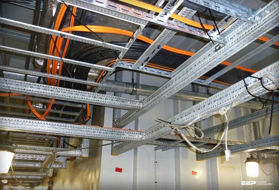
Figure 1 depicts a high-level cable route in an industrial structure. A cable ladder is supplied to transport distribution cables feeding switchboards located at a distance from the site substation. A cable basket with three independent compartments is supplied for data cabling, while a cable tray is given for final circuits feeding lighting and machines.
Figure 1 – A high-level cable route in an industrial structure

2. Wise Selection of Cable Runs
It is important to position cables and other conductors in such a way that they are not vulnerable to deterioration caused by factors such as mechanical damage, vibration, moisture, corrosive substances, oil, and heat. In situations where such conditions cannot be avoided, it is mandatory to install an appropriate wiring system.
Four instances are:
- Mineral Insulated (MI) cables which will withstand water, steam, oil or extreme temperature,
- LSF or PVC covered Mineral Insulated (MI) cables which will withstand, in addition, chemicals corrosive to copper,
- XLPE up to 90 degrees Celsius, and
- PVC/SWA/PVC sheathed cables will withstand most of these conditions and operating temperatures up to 70 degrees Celsius.
The maximum temperatures at which various types of cables are considered safe to operate are extremely important.
If the operating temperatures are higher than 150 degrees Celsius, you will need to use heat-resistant cables, such as varnished glass fiber, which can withstand temperatures of up to 250 degrees Celsius. Additionally, in areas with extremely high temperatures, the conductors will need to be made of materials with a high melting point, such as nickel or chromium copper, or silver-plated copper.
It is important to keep in mind that the ambient temperature in which cables are installed has a significant impact on the maximum allowable current that they can carry.
The flexible metallic conduit eliminates the need to disconnect the connections before removing the thermostat or another device.
See Figure 2. The bulk of the wiring is housed in rigid steel conduit, while heat-resistant wire in flexible conduit is utilized for connections near the boiler.
Figure 2 – Electrical installations in a boiler room

2.1 Cables Exposed to Corrosive Liquids
PVC-insulated cables are the kind that should be used whenever possible when installing cables in locations that are at risk of contact with acids or alkalis. It is strongly recommended that you do not use any covering made of metal.
In a similar vein, steel conduits or any other systems that make use of ferrous metals should not be utilized in areas close to saltwater.
Figure 3 – Corroded cables

2.2 Cables Exposed to Explosive Atmospheres
When conductors are placed in environments that are flammable or that contain explosive atmospheres, further safety measures are required to be performed. Electrical equipment that may reasonably foreseeably be exposed to hazardous environments should be of such construction or as necessary protected as to prevent, so far as is reasonably practicable, danger arising from such exposure.
Electrical equipment should be of such construction or as necessary protected as to prevent, so far as is reasonably practicable, danger arising from such exposure.
The BS EN 60079 standard needs to be followed for installations of this kind. Installations for gasoline service pumps and storage depots are regulated by the standard IEC 62282-3-100.
Suggested Reading – Failure cases of LV/MV electrical equipment and what should have been done (to avoid them)
Failure cases of LV/MV electrical equipment and what should have been done (to avoid them)
3. Preventing the Spread of Fire
Fire alarm systems, evacuation routes, and smoke containment are just a few of the many factors that must be taken into account. In order to prevent the spread of fire, it is imperative that no openings be left in the floors or walls of a structure during the installation of conduits, trunking, or cables.
A fire might easily spread through a building with vertical cable shafts or ducts. If you have to carve slots or holes in the floor or wall to run cables, be sure to fill them with noncombustible material.
At each level, fire barriers made of non-combustible material must be installed inside of any vertical cable ducts or trunking. At each level, you’ll need to patch the slots or holes through which the conduits or trunking flow. Internal, non-combustible barriers not only prevent fires from spreading but also prevent hot air from rising and pooling at the duct’s top.
Figure 4 depicts fire suppression in vertical cable duct. Where the trunking of a vertical cable duct passes through floors, fire barriers are installed, and the floors are patched with cement. There are specialized fire barrier materials that are elastomeric in nature and expand in response to fire.
Figure 4 – Vertical cable duct fire barriers

4. Identification of Conduits and Cables
The IEE Regulation 514.1.2 stipulates that wiring must be marked in order for it to be recognized when it is subjected to inspection, testing, repair, or modification. Table 51 of the IEE Regulations provides comprehensive information regarding standardized cable colors.
Since the harmonisation, the colors brown, black, and grey have been used for the phase conductors L1, L2, and L3, respectively, in fixed cables. The color blue has been used to represent the neutral, while green and yellow are used for the protective conductors.
When modifications are made to an existing installation, it will be immediately apparent that due to the fact that blue was originally one of the phase colors, caution will be required when installing new wire because blue was formerly one of the colors. Warning signs are required to be displayed by any installation that makes use of both the “old” and the current color systems. This is a requirement.
Figure 5 – An extension of this installation will result in a color combination based on old and new standards. A cautionary message must be displayed.

It is required to post a warning notice worded as illustrated in any installation where wiring changes result in a mixing of colors from old and current standards. This should be installed ‘at or near the appropriate distribution switchboard‘.
Conduit colors are defined, and when painting is possible, they should be orange. The incoming power supply and distribution cables should also be labeled with the nature of the power supply, the number of phases, and the voltage.
Figure 6 – A warning notice about wiring changes

5. Cables in Low-Temperature Areas
Some PVC-insulated cables can be used in temperatures as low as -30 degrees Celsius and -40 degrees Celsius. The data provided by the manufacturer should be consulted in order to determine the lowest temperature at which a specific cable type can be used safely.
However, cables should not be installed anywhere during times when the temperature is below 0 degrees Celsius since the insulation is susceptible to cracking if it is handled in very low temperatures.
In freeze environments, the incorrect pattern of jacket damage is common. Jacket damage is the deterioration of the outer sheath of a cable. Hardening and shattering of the jacket reveals the stranding or shield beneath. The improper jacket material is often chosen for these kinds of uses.
When a cable’s jacket is damaged, the mechanical protection it provides to the cable’s cores is compromised, necessitating prompt replacement.
Figure 7 – Cables in freezing areas

6. Single-Core Cables
AC circuits shouldn’t be wired with single-core wires that have been wrapped with steel tape or wire for protection. However, there are situations when employing single-core cables might be advantageous. One example of this would be using cables with a diameter of 630 mm2 to connect the supply transformer and the main switchboard panel.
In such a scenario, the application of aluminum wire armoring (also known as AWA) is entirely appropriate.
Good Reading – Hints for a good design of an optical communication system for a transmission line network
Hints for a good design of an optical communication system for a transmission line network
7. Bunching of Outgoing and Incoming Cables
Excessive induction losses will not take place if the outgoing and incoming cables of a two-wire AC circuit, or all of the phases and neutral of a three-phase circuit, are encased in the same conduit or armored cable. This prevents the loss of energy due to excessive induction. It is necessary to bundle single-core cables that are protected by conduits or trunking but do not have armor. This is done so that both the outgoing and incoming cables are protected by the same conduit or trunking.
This must be accepted as a general rule for all AC circuits, and it must be assured that no single conductor is surrounded by magnetic material such as steel conduit, trunking, or armoring. This is a requirement for all AC circuits. The reason for this is because any single-core cable that carries an alternating current induces a current in the metal that is surrounding it.
This current has a tendency to work against the flow of the initial current.
When it is needed to use single-core cables in a particular application and the protection of conduit or trunking is required, consideration should be given to the use of non-metallic enclosures. This is the case when it is essential to use single-core cables. There is a selection of plastic conduit and trunking systems available to choose from.
There are times when the requirement to take measures against induction is ignored, and here are some of those times. One example of this is when single-core cables are routed into busbar chambers, distribution boards, or switchgear. Circulating currents can be created in these locations if the single-core cables are carrying alternating currents and are routed via different holes in a metallic enclosure.
In the past, producers of switchgear and electric motors would drill three different holes in the casing of their products so that the circuits could accommodate three phases.
In the event that it is not possible for all of the cables to fit through a single hole, non-ferrous or aluminum gland plates must be utilized; alternatively, the space in between the holes should be slotted.
See Figure 8.
If it is not possible for single-core cables that are carrying heavy alternating currents to pass through the metal casing of a switch, terminal box, or other similar equipment through a single hole, then the space between the holes should either be slotted or fitted with a non-ferrous gland to prevent circulating currents. Both of these options are intended to prevent circulating currents from occurring.
Figure 8 – Prevention of circulating currents from occurring single-core cables carrying heavy alternating currents

In situations in which steel wire armored cable is going to be utilized, preventing circulating currents might be accomplished by earthing only one end of the main cables. It goes without saying that a separate circuit protection conductors should be installed.
9. BONUS! A Practical Guide To The Wiring Regulations (PDF)
Download Practical guide to the wiring regulations (for premium members only):
Reference: Modern Wiring Practice by R.A. Beck and T.A. Stubbs
Related electrical guides & articles


Edvard Csanyi
Hi, I'm an electrical engineer, programmer and founder of EEP - Electrical Engineering Portal. I worked twelve years at Schneider Electric in the position of technical support for low- and medium-voltage projects and the design of busbar trunking systems.I'm highly specialized in the design of LV/MV switchgear and low-voltage, high-power busbar trunking (<6300A) in substations, commercial buildings and industry facilities. I'm also a professional in AutoCAD programming.
Profile: Edvard Csanyi
