Generator Protection Issues
Protecting a generator requires more than just a single relay. It’s a system that includes auxiliary relays, communication with SCADA or similar systems, wiring from CTs and PTs (sometimes called VTs), and protective relays, which can be standalone devices or part of multifunction units.

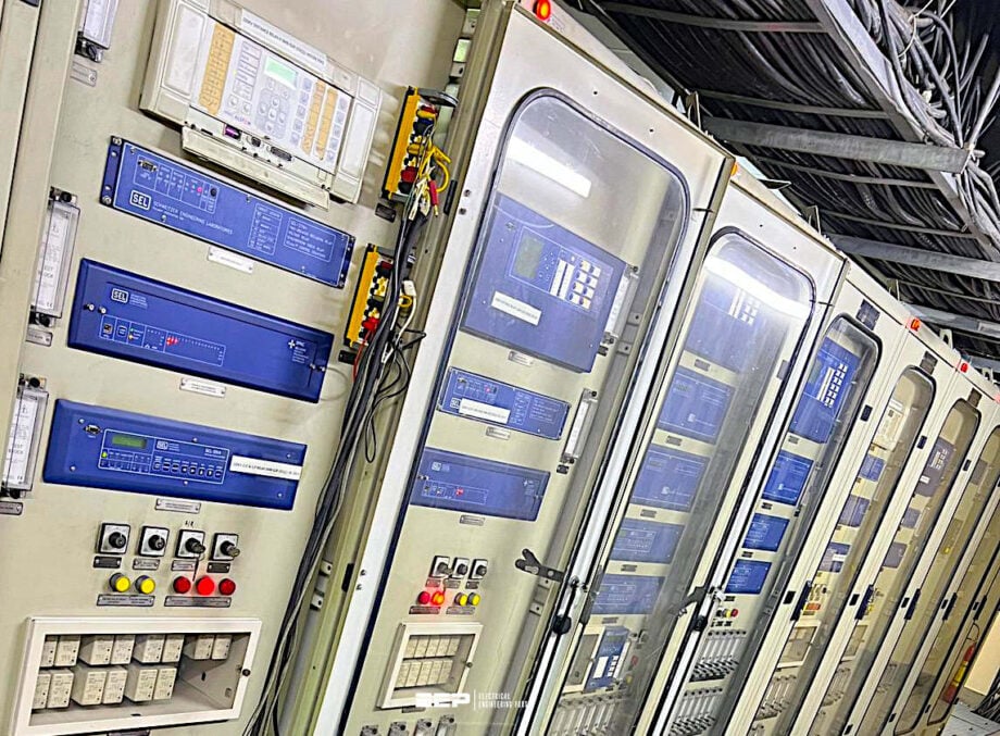 Mistakes in generator protection that operators often make (photo credit: Salman-Javid via Linkedin)
Coordination with other comparable systems is also an important part of protection, as it ensures that the removal of one malfunctioning piece of equipment from the grid by means of a single relay or protective function does not cause the unnecessary removal of other equipment.
Last but not least, safeguarding a generator also includes all the necessary configurations to guarantee correct relay operation and synchronization. Therefore, a protection system can only work properly if all the relays are in sync and the settings for each one are correct (protective function).
Because they don’t go off very often, protective mechanisms are sometimes disregarded. As a result, maintenance is not given the attention it needs, which could lead to serious problems.
Furthermore, for the really large generator units, the time it takes to identify an appropriate replacement following an unexpected catastrophic failure may be measured in months, if not years.
Plant staff must be informed on the significance and operation of each protective device, and power plants must maintain an effective predictive maintenance schedule for their protection systems.
- Identifying the Various Protected Zones
- How to Identify Probable Causes from the Actuation of Protection Relays
- Essential Checks before Returning a Unit to Service after a Protection Trip
- Essential Checks before Returning a Unit to Service after Receiving an Alarm
- Alarm Response Procedures:
- Attachment (PDF) 🔗 Download ‘The Synchronous Generators Handbook’
1. Identifying the Various Protected Zones
In Table 1, the column titled Protected Zone or Equipment identifies the reach and coverage of a given protective function. Equipment pinpoints to the protected gear, which in this case always includes the generator. On the other hand, zone relates to all the equipment (apparatuses, lines, cables, etc.) that if experiencing a fault, will activate the protective function relay.
The zone can be seen as also in a geographical context. For instance, a distance relay is called as such because its activation zone can be given in kilometers (of transmission line).
In the case of a differential protection, the zone will be all that is between the current transformers (CTs).
Table 1 – Protection functions and protected zone/equipment
| Device number | Protective function | Protected zone or equipment |
| 15 | Speed or frequency-matching device | Provides some positive feedback during the critical activity of synchronizing to the grid, thus protecting the generator. |
| 21 | Distance protection – Backup for generator zone phase faults | Protects generator, isolated phase bus (or lead cables) up to and including the HV winding of the step-up transformer and auxiliary transformers. Reach may be more or less than that, depending on the relay’s settings. |
| 24 | Volts/Hertz protection – Senses an overfluxing condition | Protects generator stator core and step-up and auxiliary transformers’ cores from damage due to overfluxing. |
| 25 | Synchronizing or sync-check protection – Works together with the #15 function to facilitate smooth synchronization. | Protects generator and turbine components from malsynchronization. |
| 27 | Undervoltage protection – Senses a condition where the voltage of a given bus is below a normal range. | Protects generator from synchronizing on a dead bus. Mainly used to sense a loss of voltage in the station auxiliary systems. It may alarm and in some cases initiate an automatic bus transfer activity. |
| 27H | Undervoltage protection at the generator neutral – Senses condition where the third harmonic component of the neutral voltage is below certain level. Some schemes use 59H (a third harmonic overvoltage relay operating in reverse mode, accomplishing the same thing). | Protects the stator winding and stator core from grounds. It may also reacts to grounds in the lead cables, as well as the low voltage windings of the step-up and auxiliary transformers. |
| 32 | Reverse power protection – Reacts to a condition wher the actibe power flow is from the grid to the generator, | Protects from motoring of the generator, either as a synchronous or induction machine. It can be part of a scheme to separate the unit from the grid in an orderly manner to avoid overspeed, as part of a sequential tripping scheme. |
| 40 | Loss-of-field protection – Senses the condition when excitation is too low to maintain synchronous opertion with the grid. | Protects many generator components from a loss of synchronization. Fault may be located anyway in the excitation circuit, including field winding, brushgear (if brushed), exciters, rectifiers, excitation cables or buses, AVRs and any other excitation component. Result of loss of field is the generator operating as an induction generator. |
| 46 | Stator unbalanced current protection – Senses condition when the stator negative-sequence current is higher than a given threshold. | The protected components are the rotor forging, wedges, retaining rings, and parts of the amortisseur. |
| 49 | Stator thermal protection – Senses when the temperature of various stator components (core, winding, etc.) is above the normal range. | Protects specific components where the TCs and/or RTDs are mounted. |
| 50/51 | Instantaneous/timed overcurrent protection – Reacts to sudden and/or large increases of stator current due to short circuits. | Protects the generator from large overcurrent events. |
| 50GN/51GN | Instantaneous/timed overcurrent protection at secondary of the grounding transformer – Reacts to sudden and/or large increases in neutral current. | Protects the stator winding from faults in the generator and generator voltage system that result in sudden and/or large ground currents through the neutral of the generator. |
| 50BF/51BF | Overcurrent function used as part of the circuit breaker-failure scheme. | Protects the main generator (and transformers if the main breaker is on the HV side of the SUT) for a case when the generator breaker fails to open during a fault clearing operation. |
| 51TN | Time overcurrent protection – Reacts to currents above normal range flowing via the neutral of the wye-connected HV winding of the SUT. | Protects the SUT from ground faults in the SUT and HV systems. Protects the generator from large negative-sequence currents due to short circuits on the SUT or close by on the grid. |
| 51V | Voltage-controlled (voltage-restrained) time overcurrent protection – Reacts to short circuits in the vicinity of the station and at the station. | Protects the generator from short circuits at the station or on the grid, in close vicinity to the station. The reach into the grid can be set, so not to trip the unit unnecessarily for far-away faults that otherwise would trip the 51 overcurrent relay. |
| 59 | Overvoltage protection – Reacts to output voltages above the rated maximum (typically: 105% of rated). | Protects the generator from overvoltage and overfluxing. When part of the protection scheme, it is normally used only to alarm. |
| 59GN | Overvoltage protection – React to an increase in voltage in the secondary of grounding transformer. | Protects the stator winding from ground faults in the generator and generator voltage systen that result in grounf currents through the neutral of the generator (and thus voltage increase across the secondary’s resistance). The fault may be located anywhere between the neutral of the generator, including the grounding transformer, to the delta connected windings (generator side) of the SUT and auxiliary transformer(s). |
| 59BN | Zero-sequence voltage protection – Senses a ground fault on an otherwise ungrounded bus. Also known as 59BG. | During backfeeding via the SUT with the generator breaking or generator links open, this function protects the equipment from a short circuit to the ground. The protected zone includes all the equipment between the open links or breaker to the delta-connected windings of the SUT and auxiliary transformer(s). |
| 60 | Voltage balance protection – Detects blown PT fuses or open secondary circuits. | Protects the generator against an unnecessary trip due to loss of a PT fuse or open secondary circuit. Most probably, the fault will be with the PT circuit (such as a fuse, short-circuit between secondary wires and/or to ground, or an open secondary circuit). |
| 62 | Time overcurrent protection – Detects turn-to-turn faults in generator windings. | Protects stator against shorted turns in the stator winding. Mainly in hydraulic-driven generators or small turbogenerators. Large turbogenerators have a single turn; thus this protection is not used. |
| 62BF | Circuit breaker failure protection | Protects the main generator (and transformers if the main circuit breaker is on the HV side of the SUT) for a case when the generator circuit breaker fails to open during a fault-clearing operation. |
| 64F | Ground detector based on voltage sensing – Detects grounds on the excitation power circuit. | Protects against short circuits to ground on the excitation power circuit. The fault can be on the rotor winding, brushgear, dc cables/busses, or exciter. |
| 64S/64R | Ground fault protection of stator/rotor based on voltage injection. | Protects 100% of stator rotor against ground faults. |
| 67 | Phase directional overcurrent protection – Detects flow of current toward the generator. Used as part of the inadvertent energization scheme. Also implemented by a combination of 50/27 functions. | Protects the unit against inadvertent energization while standing still or on turning gear. |
| 78 | Loss of synchronism protection | Protects the generator against a loss of synchronism. Can be considered backup to the loss of field relay (#40). |
| 81 O/U | Over/under frequency protection – Detects deviation from the nominal frequency. | Protects the unit components from operating at frequencies other than the rated frequency of the unit. |
| 86 | Hand-reset lockout auxiliary relay | Used to lock the system following the operation of a protective relay. Must be reset manually. |
| 87G | Differential protection of the generator | Protects the generator from short circuits between phases on the stator winding. Protection zone includes the stator winding and the portion of bus/bushings between the CTs connected to the 87G at both sides of the unit. |
| 87T | Differential protection of the SUT, or AUTs | Protects the transformer against a phase-to-phase fault inside the transformer. The wye-connected winding will also operate for a phase-to-ground fault. |
| 87U | Unit differential protection – Also indicated as 87O in some protective schemes. | Protects the generator, SUT, AUTs, and HV breaker for a phase-to-phase short circuit. Protected zone where fault is located is between the CTs connected to the 87U. |
| Excitation protective functions | The exciter and AVR most often have built-in a number of protective functions, such as the maximum excitation limit, minimum excitation limit, and maximum V/Hz limit. | Protects the generator against overexcitation and overfluxing events, as well as operation outside the capability curve or below the steady-state stability limit. These protective functions must be set in such a manner that they coordinate with the other protective functions shown in this table. |
Where:
- SUT – Step-up transformer
- TC – Termocouple
- RTD – Resistance temperature detector
- AUT – Auxiliary unit transformer
Figure 1 depicts the zone protected by the generator differential protection (87G). A fault between phases on the busses, windings, generator circuit breaker, and IPB 5 (or lead cables) between the CTs, will cause the 87G to actuate. Faults on either CT or wiring between CTs and the relay (secondary circuit) may also cause actuation of the relay.
Obviously a failure of the relay itself may cause an unintended actuation.
Figure 1 – Generator differential protected zone

The MV generator circuit breaker (CB) is included in the protected zone. The neutral grounding transformer is shown between the generator’s neutral point and earth, and is not included in the protected zone.
Neither is the Step-up Transformer (SUT).
Figure 2 depicts the zone protected by the generator differential other nondedicated protection relays when the breaker is on the high-voltage (HV) side of the step-up transformer (SUT). As can be seen by inspection of the Figure 2, in this scheme the generator breaker is not included in the protected zone; only the main generator is.
Comments related to the CTs, secondary circuit, and relay integrity remain as explained above.
Figure 2 – Generator differential protected zone

The generator circuit breaker (CB) is not included in the protected zone of the generator differential (87G), but is included in the protected zone of the unit differential protection (87U).
Figure 3 shows the zones protected by the 87G and 87U differential protection relays (protective functions), respectively.
In practical terms, the unit differential protection will, in most cases, also include the auxiliary transformers.
Figure 3 – Generator differential and unit differential protected zones

Figure 4 shows the zone protected by a distance relay, such as the one implementing protective function #21, or obtaining a similar goal with a voltage controlled current relay (51V).
Figure 4 shows the case where the reach includes the medium-voltage (MV) winding of the SUT.
Figure 4 – Zone protected by a backup distance protection relay

Another example of protected zone is shown in Figure 5. In this case the turbine(s) is (are) included together with the generator, as well as any other not-shown rotating component in the unit’s train, such as a rotary exciter. Moreover, even motors supplied via auxiliary unit transformers (not shown on the figure) are also protected for abnormal frequency when the circuit breaker is tripped.
In this case, changing relay settings will not change the protected zone, but will change the threshold values that will trigger actuation of the 81 under/over frequency relay.
Figure 5 – Zone protected by an over/under frequency relay

Figure 6 shows the protected zone by the stator ground protection. Typically, the stator ground protection is implemented at the secondary of the grounding transformer by an overcurrent relay and/or an overvoltage relay.
Also, a third harmonic relay is commonly applied. In later years, stator ground protection has been implemented by the third harmonic relays monitoring the third harmonic voltages at both the neutral and lead side of the machine.
Finally, low-frequency low-voltage signal injection is also used as an active circuit implementation of a stator ground fault detection technique covering 100% of the stator winding.
Figure 6 – Zone protected by a stator ground protection relay

Figure 7 shows the case, typical of some small peaking units, or some Combustion turbine generators (CTGs), where two or more generators are connected to a single bus before the SUT. In this case, the ground protection relays may not distinguish a ground fault on one generator from a ground fault on the other generator.
Some protection devices, such as the V/Hz (overfluxing) protection (24), protect very specific components of the generator and/or other unit equipment. In the case of the V/Hz protective function, the protected zone includes the generator core, as well as the core of all auxiliary transformers and the step-up transformer.
Figure 7 – Zone protected by stator ground protection

Figure 7 – Zone protected by stator ground protection
A ground fault anywhere in the protected zone will result in activation of the ground relay. Positive identification of a stator ground as belonging to one or the other alternator may be impossible with most protection schemes.
Negative-sequence current protection (46) protects some rotor components that are at, or close to, the surface of the rotor. It can also protect against metal fatigue of long turbine blades, such as those encountered in large low-pressure turbines of nuclear-powered generators. Another example of generator/turbine zone protection is tripping for pole slipping, which can also damage the long blades that are mounted on the last-stage of the turbine.
Synchronizing (25) and sync-check (15) relays protect the entire train from damage due to malsynchronization. Windings, couplings, bearings, forging, turbine blades, and other components are prone to damage or degradation due to a bad case of synchronizing out of step.
The examples above are not exhaustive; there are a number of protective functions that are not covered. Nevertheless, the reader can obtain their protective reach (zone) in the form of equipment covered, by following the same method of analysis employed above.
Further Study – Electrical Testing and Commissioning Handbook
2. How to Identify Probable Causes from the Actuation of Protection Relays
Unfortunately, it is not uncommon for plant personnel to misinterpret the causes for a generator trip initiated by the protection system. Sometimes, this leads operators to close the circuit breaker on a remaining fault, causing additional damage that could have been avoided. This results in needless additional delays in returning the unit to operation because of late discovery of the faulty component.
For example, meggering the stator after a V/Hz event and subsequent trip will not provide any insight onto the condition of the stator core, which is the component most prone to failure due to overfluxing.
Similarly, looking for a short circuit in the switchyard immediately after the stator ground protection relay has actuated, probably is not the most effective way of addressing the problem.
Where to start looking, or what to start testing, is a key factor in setting the duration of the forced outage.
For instance, carrying out an insulation resistance test of the stator winding requires separating the generator winding from the neutral transformer, and removing links to the isophase bus (IPB) in generators without a generator breaker.
Figure 8 – Generator breaker

These activities add time to the outage. If a high potential test is desired, the amount of disassembly required to perform the test might be greater. It would be a waste of time to do all of that if careful analysis of the protective relay(s) actuation indicates that the fault is somewhere else other than on the stator.
The rational approach is to first look inside the protected zone(s) of the actuated protective relay(s) that tripped and/or flagged.
Nevertheless, in most cases careful inspection of the protected zones of the actuated relays, in addition to the sequence of events (hopefully recorded by the unit’s DFR 8 or similar instrumentation), serves as a compass in the search for the faulty component and fault location.
Figure 9 shows how the protected zones activated during a fault determine the most logical place to initiate the search.
Figure 9 – Three protected zones: by the 87G generator differential protection relay; by the 87U unit differential protection relay and by the 21 distance protection relay

Shown on the figure are three protected zones: by the 87G generator differential protection relay; by the 87U unit differential protection relay and by the 21 distance protection relay.
If all three relays trip, or if some trip and the others flag, for a phase-to-phase short circuit inside the generator, then the red dotted area represents the intersection of all three zones, and it the most probable to contain the fault.
Obviously after a severe fault, a conservative approach may include some testing inspection of equipment outside the protected zone (e.g., that may be affected by large through short-circuit currents).
Some protective functions provide coverage to very specific components of the generator.
For instance, Figure 10 shows the protected zone (rather the protected components) by the overfluxing (V/Hz) relay (24). In this particular and unfortunate case, although the components that may be directly impacted are easily identified, the level of degradation is much more difficult to determine.
Figure 10 – The equipment protected by the volts-per-hertz relay

The relay also protects the cores of transformers, because in this case the main breaker is on the HV side of the SUT.
Figure 11 shows a conceptualization of the process by which the location of a faulty component may be found. Table 1 provides the reader with hints as to what might be the most probable location of the fault of damaged components. For additional information on all protective functions.
Figure 11 – The intersection of the protected zones provides a clue as to where the fault might have happened

3. Essential Checks before Returning a Unit to Service after a Protection Trip
As mentioned in the previous sections, it is not unheard about a unit being restarted after a protection-initiated trip, without an exhaustive investigation of the causes that led to the actuation of the protective relay(s).
The spurious trip explanation is often overused, resulting, in some cases, in very serious damage to the equipment, not to mention compromising the safety of the personnel. Having hand-reset lockout relays for internal malfunctions, and self-reset relays for grid-related faults goes some distance in addressing this concern.
It behooves each generating station to have clear written procedures outlining the process operators and technical personnel must follow before returning a unit to service, following a trip initiated by its protection system.
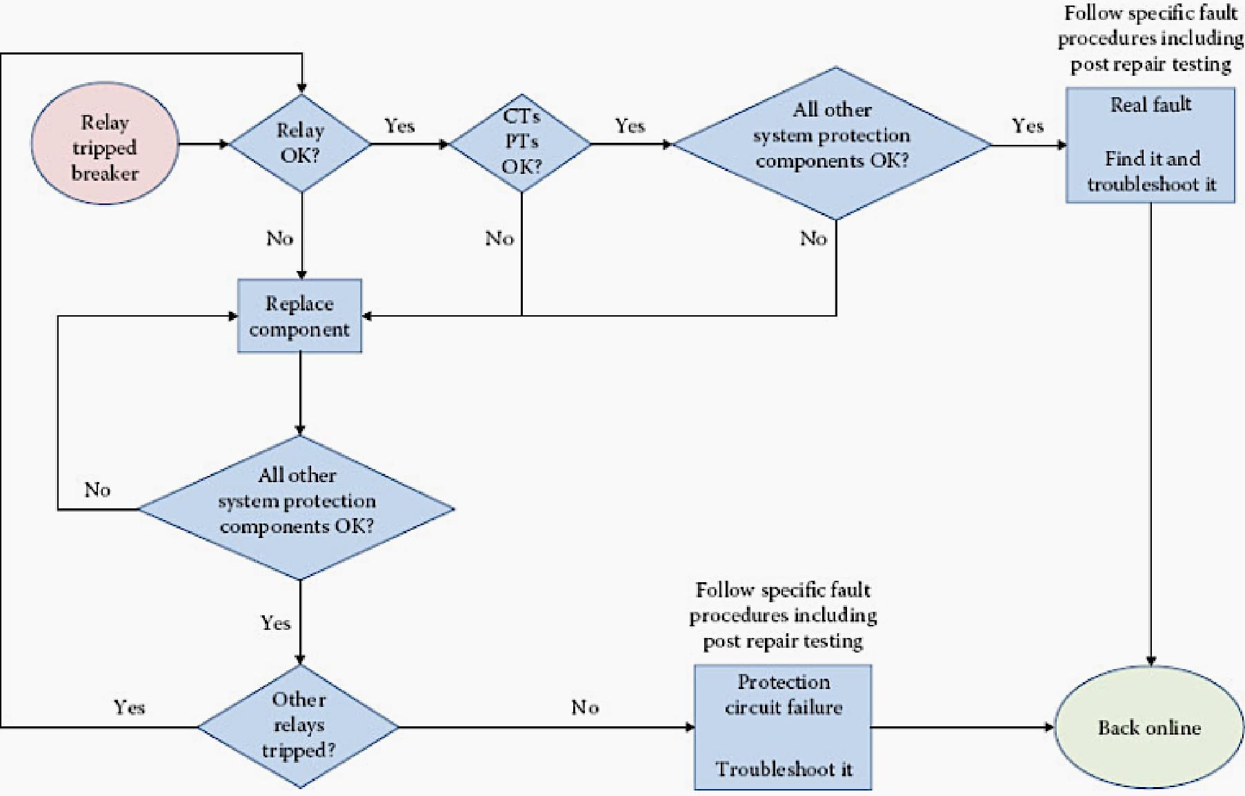
Figure 12 depicts a possible algorithm representing steps to be taken after a generator unit is tripped by its protective relays, to assure that the machines are returned to operation without having first investigated and the cause for the trip removed.
Figure 12 – A possible algorithm representing steps to be taken after a unit is tripped by its protective relays
4. Essential Checks before Returning a Unit to Service after Receiving an Alarm
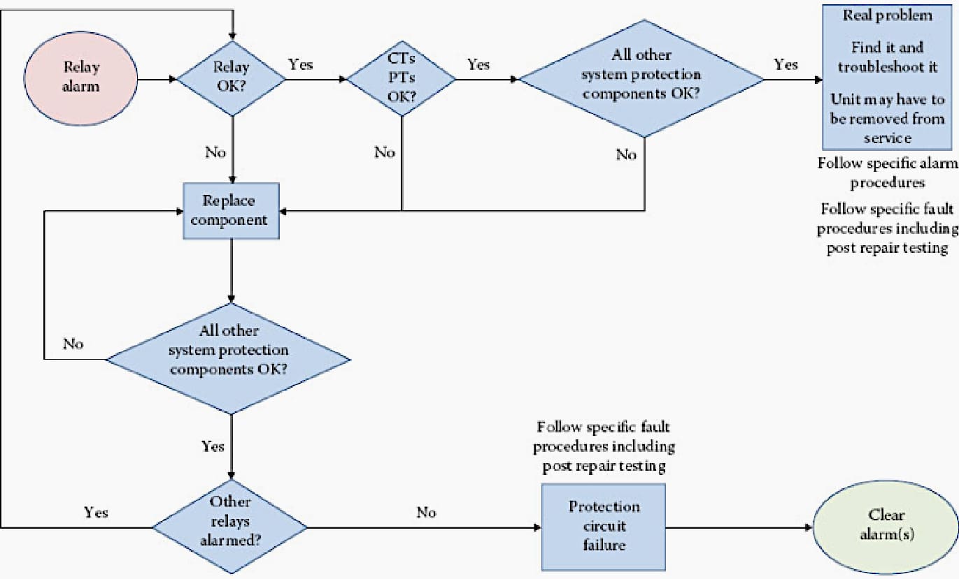
Figure 13 presents an algorithm that may be part of every alarm-response procedure in a power plant. The algorithm offers a due diligence method that prevents misdiagnosing an alarm as spurious or due to a bad sensor, or some other nonchalant reason, and therefore averting a degraded component condition from developing into a major fault.
Unfortunately, it is not uncommon for alarms generated by the protection system to be dismissed as not being the result of a real malfunction within the equipment.
Nevertheless, even in this case the proper process should be followed to vet the protection system and the unit as being fit for remaining online.
Suggested Course – Generator Protection Concepts, Applications & Relay Protection Schemes

5. Alarm Response Procedures
During the many years of work with power plants of all types, there are instances in which there was a glaring lack of written procedures addressing how operators should react in the presence of certain alarms. In some cases the response is by the seat of the pants. Unfortunately, this approach sometimes leads to undesirable results.
Written alarm-response procedures are helpful in averting the inconsistency in the responses to the same alarm by different operators, and to allow for a thought-out approach leading to minimum disruption to production and/or equipment damage.
The next few subsections discuss just a few of those alarms that are often found without having clear written instructions on how to dispose of them.
Suggested Study – The true art of control, monitoring and protection provided by Substation Automation Systems
The true art of control, monitoring and protection provided by Substation Automation Systems
5.1 Rotor Ground Faults
There are numerous and very diverse practices among power plants for responding to rotor winding ground faults. Some units are tripped automatically for a field ground that reaches a given value (e.g., 1000 Ω), others immediately start troubleshooting the problem, and the unit is manually removed from service if the fault cannot be fixed or fixed within certain time limits, and some others are left to run for long periods of time (even months) before the problem is addressed.
This last approach has led, more than once, to serious damage to the field (rotor) from a subsequent second ground, given the likelihood for a second ground developing increases after a first short circuit to ground establishes a ground reference.
Figure 13 – A possible algorithm representing steps to be taken after an alarm is generated by its protective relays, to assure that the machine and protective system are reliable for continuing operation online
5.2 Winding Temperature
One unfortunate recurring avoidable situation is when operators misinterpret elevated winding temperatures as being the result of faulty probes (RTDs or TCs), even in cases where these readings are accompanied by that of other sensors, such as generator condition monitor alarms.
This has led, in some cases, to major damage requiring months of downtime and large capital expenditures for repairs.
This is one of those situations where a well-written procedure can prevent undesirable consequences. The procedure should be written well in advance, with solid engineering input and managerial acquiescence, and without the time pressure encountered during a developing problem.
Related Study – Power protection study for a network with ten buses, five transformers, two generators and motors and six transmission lines
5.3 End-Winding Vibration
Another area where practices deviate significantly from each other is when addressing elevated end-winding vibrations. On most generators there are no sensors installed providing online vibration measurements; thus, operators have no knowledge of what is going on with their machine’s endwindings.
By the time it becomes clear that the endwindings may be experiencing high vibrations (through visual inspection and/or testing during outages), serious degradation might have occurred.
In those fortunate cases where units have installed end-winding vibration sensors that allow measuring of the end-winding vibration online, many do not take advantage of the existence of the probes to read and trend the vibration, and those that do trend them, in certain occasions do not have clear written procedures about limits and adequate remedial actions.
Further Study – Improving efficiency and reducing the vibrations of large industrial electrical machines
Improving efficiency and reducing the vibrations of large industrial electrical machines
5.4 Rotor Vibration
This is also an area where there is a very diverse approach to how to address the problem of increasing vibrations. Most, if not all, generators have sensors installed that provide online realtime measurement of rotor vibrations; most even follow the same international standards.
However, there are differing approaches about how they respond to a significant increase in vibrations. This is also a good example where having written procedures in place addressing the problem of increasing vibration levels can be very helpful in a time of need.
Recommended Course – MATLAB Simulations using Simulink for Power Electronics, Electric Motors, Generators and Solar

6. Attachment (PDF): The Synchronous Generators Handbook
Download: The Synchronous Generators Handbook Calculations (for premium members only):
References: LCSH: Turbogenerators–Maintenance and repair by Isidor K. and Geoff K.
Related electrical guides & articles


Edvard Csanyi
Hi, I'm an electrical engineer, programmer and founder of EEP - Electrical Engineering Portal. I worked twelve years at Schneider Electric in the position of technical support for low- and medium-voltage projects and the design of busbar trunking systems.I'm highly specialized in the design of LV/MV switchgear and low-voltage, high-power busbar trunking (<6300A) in substations, commercial buildings and industry facilities. I'm also a professional in AutoCAD programming.
Profile: Edvard Csanyi