
The art of understanding schematics
In the intricate landscape of electrical engineering, the ability to decipher and interpret schematic drawings is a skill that separates the adept from the novice. This technical article delves into the art of understanding schematics, unraveling the complexities through a comprehensive exploration of various essential components and their functionalities.
 A roadmap for engineers seeking mastery in the language of electrical schematics (photo credit: EEP - Electrical Engineering Portal)
From the fundamental workings of Voltage Transformer Circuits to the nuanced precision of Magnetic Contactors, and from the diverse types of Auxiliary Contacts to the strategic intricacies of Multi-Position Switches, this article is a roadmap for those seeking mastery in the language of electrical schematics.
In this article, the journey begins by demystifying Voltage Transformer Circuits, providing a foundational understanding of the underlying principles. Moving forward, we explore the indispensable role played by Magnetic Contactors in electrical systems, shedding light on their power and precision.
The discussion then branches into the realm of Auxiliary Contacts, covering their types, applications, and the critical role they play in diverse electrical setups.
As we navigate through the technical intricacies, we unravel the significance of Limit Switches, the subtleties of Early Make and Late Make Auxiliary Contacts, and the precision of Early Break and Late Break Contacts. The exploration extends further into the domain of Multi-Position Switches, providing insights into their design considerations and applications.
A pivotal segment of the article is dedicated to Tripping and Closing Coils, crucial elements in the functionality of circuit breakers. The discussion extends to Coil-Saving Contacts, shedding light on their role in enhancing safety and efficiency in electrical systems.
The latter part of the article scrutinizes the functionality of Normally Open and Normally Closed Contacts, specifically in the context of Coil-Saving Circuits. These contacts, often overlooked but inherently significant, play a key role in preventing wear and tear on critical components.
This technical article actually continues the Electrical Schematics series and I advise you to read and study first two parts:
By delving into the intricate details of each topic, this technical article aims to empower readers with the knowledge needed to navigate and comprehend complex schematic drawings.
Whether you are an aspiring electrical engineer or a seasoned professional seeking to deepen your understanding, this article serves as a comprehensive guide, unraveling the mysteries behind the symbols and lines that define the language of electrical schematics.
If you didn’t already, I advise to take a cup of coffee! So, let’s get started!
- Voltage Transformer Circuit
- Unveiling the Power and Precision of Magnetic Contactors in Electrical Systems
- Types of Auxiliary Contacts
- Limit Switch
- Early Make and Late Make Auxiliary Contacts
- Early Break and Late Break Contacts
- Make Contact Delayed When Closing & Make Contact Delayed When Opening
- Multi Position Switch
- Tripping and Closing Coils
- Coil Saving Contacts
- Functionality of Normally Open and Normally Closed Contacts for Coil Saving Circuit
- BONUS! Download Complete Schematic Drawings for 132kV Line-1 (=E01) Relay Panel +RP3 (PDF, 30 pages)
1. Voltage Transformer Circuit
The voltage transformer is a device used to step down voltages, making it easier for protection and control devices to handle. In my experience, I have encountered two standard secondary voltages for voltage transformers: 110 volts and 100 volts. These secondary and primary ratings are provided in terms of line-to-line voltages, and sometimes the square root of 3 is included under line voltages to represent the phase-to-ground voltages.
The configuration of voltage transformers can be three-phase, two-phase, or three-phase in the system, depending on the specific requirements.
This zero sequence voltage is primarily utilized with directional overcurrent and earth fault relays.
Figure 1 – Voltage transformer connection for zero sequence voltages

Refer to Figure 2, which depicts the placement of the voltage transformer in a Gas Insulated Substation (GIS) and its representation in the single-line gas compartment diagram.
It is crucial to note that the positioning of the voltage transformer at the cable side implies that, even when the line isolator is in the open position, the voltage transformer will remain energized as long as the cable is energized.
Figure 2 – Voltage transformer representation in Gas Insulated Substation (GIS)

This unique configuration allows for the utilization of VT voltages in interlock circuits. For instance, when the line is energized, the interlock can be designed to prevent the closure of the line earth switch.
Understanding the intricacies of the single-line diagram becomes imperative in this context, as it provides a comprehensive view of the system’s configuration and aids in making informed decisions regarding interlock circuits and safety measures.
In ensuring the safety and operational flexibility of the voltage transformer circuit, the incorporation of isolating links becomes paramount. Refer to Figure No: 03, which illustrates the presence of several VT isolating links.
This isolation capability proves especially valuable when tasks necessitate working under energized conditions.
Figure 3 – Three-phase VT circuit, with MCB for short circuit protection and VT terminal block for isolation facility

For instance, if the replacement of a meter or relay is required, isolating the VT circuit becomes a prerequisite, enabling maintenance or modification work to be performed safely.
Examining Figure 4 further elaborates on the features of a voltage transformer with isolation and measurement capabilities. The VT terminal block is thoughtfully designed, providing the convenience to connect banana leads.
In summary, the careful consideration of protection measures, the use of isolating links, and the integration of measurement facilities underscore the importance of precision and safety in the management of voltage transformer circuits, ensuring their reliable operation and facilitating necessary maintenance and testing procedures.
Figure 4 – Voltage transformer terminal block with isolation and measurement facility

2. Unveiling the Power and Precision of Magnetic Contactors in Electrical Systems
Magnetic contactors share similarities with auxiliary relays but differ in that they are employed where a high current rating is necessary. An exemplary application of magnetic contactors is in motor circuits, where the motor is initiated through the power/main contacts of the magnetic contactors.
Similar to auxiliary relays, magnetic contactors also incorporate auxiliary contacts. Additionally, they possess power contacts specifically designed to carry high currents, especially to withstand the inrush current experienced by motors during startup.
Therefore, the tips of these power contacts are coated with tungsten or other materials, as depicted in Figure 5, which illustrates the magnetic contactor.
Figure 5 – Magnetic contactor coil, main / power contacts and auxiliary contacts
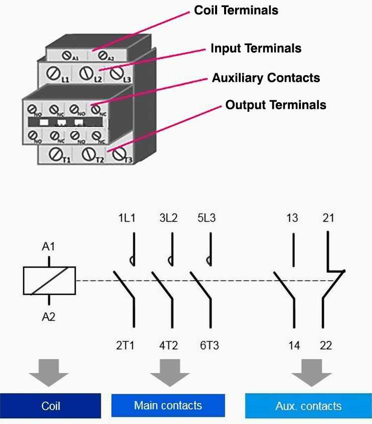
The coil of the magnetic contactor is labeled with terminals A1 and A2, while the power contacts are denoted as L1, L2, and L3, and the auxiliary contacts as 13/14 and 21/22. A notable distinction between power and auxiliary contacts lies in the tips – power contacts L1, L2, and L3 have a semi-circle, indicating their specialized treatment for handling high current.
It is important to recognize that the power contacts function as normally open contacts, and when the coil of the magnetic contactor is energized, these main/power contacts transition from an open to a closed position.
Related electrical guides & articles


Muhammad Kashif
Muhammad Kashif Shamshad is an Electrical Engineer and has more than 17 years of experience in operation & maintenance, erection, testing project management, consultancy, supervision, and commissioning of Power Plant, GIS, and AIS high voltage substations ranging up to 500 kV HVAC & ±660kV HVDC more than ten years experience is with Siemens Saudi Arabia.Profile: Muhammad Kashif
