
Key components of transformer design
One mistake and you’re done!
Managing specification and assests for large power transformers such as tank, bushings, insulation and short-circuit impedance is quite challenging. One mistake and you’re done! Power transformers play a real critical role in high-voltage transmission systems, providing strict voltage transformation, system stability, and reliable power flow, so no mistake is alowed.
 Pitfalls hidden in determining transformer tank, bushings, insulation, and impedance
Among the key components of transformer design, the tank, bushings, insulating medium, oil preservation system, and short-circuit impedance require careful consideration to ensure operational efficiency, longevity, and compliance with international standards such as IEC 60076.
This article begins with an in-depth look at the transformer tank, covering its structural functions, construction types, material selection, and pressure withstand capabilities.
It also discusses cooling arrangements, sealing techniques to prevent oil leaks, and the integration of protection and monitoring devices. Transport and handling considerations are addressed to ensure safe deployment and long-term serviceability.
The next section focuses on bushings and terminal connections, which are essential for safe electrical insulation and external connectivity. Different types of bushings—OIP, RIP, RBP, porcelain, and composite—are examined along with their mounting configurations, voltage ratings, insulation coordination, and failure mitigation techniques.
Further, the discussion extends to oil preservation systems, comparing breathing , sealed, and gas cushion methods. Design principles, functional components, and operational advantages or limitations of each system are outlined for informed decision-making.
Finally, the article examines short-circuit impedance, detailing its impact on transformer performance, fault current limitation, and system coordination. Testing methods, boundary specifications, and design tolerances are explained with reference to IEC standards.
Together, these topics provide a comprehensive technical perspective for professionals involved in transformer design, specification, and asset management.
- Transformer Tank Design:
- Functions of the Transformer Tank
- Types of Transformer Tanks
- Transformer Tank Construction and Material Selection
- Pressure Withstand Capability of Transformer Tanks
- Cooling Arrangements in Transformer Tanks
- Sealing and Leak Prevention in Transformer Tank
- Protection and Monitoring Devices on Transformer Tank
- Transport and Handling Considerations
- Bushings and Terminal Connections in Power Transformers:
- Types of Insulating Oil and Alternatives in Power Transformers:
- Mineral Oil as a Transformer Insulating Medium
- Synthetic and Natural Ester Insulating Liquids
- Silicone Oil and Its Applications in Transformers
- Gas-Insulated and Air-Insulated Alternatives
- Comparative Evaluation of Insulating Mediums
- Oil Preservation Systems in Power Transformers (Breathing, Sealed, Gas Cushion) – IEC 60076 21:
- Short-Circuit Impedance and Boundary Specifications in IEC 60076-1:
- Attachment (PDF) 🔗 Download ‘A Guide to Protection and Monitoring Power Transformers’
1. Transformer Tank Design
The transformer tank is a critical component that provides mechanical protection, structural support, and insulation containment for a power transformer. It serves as an enclosure for the transformer core, windings, and insulation oil (in oil-immersed transformers).
The transformer tank must ensure mechanical strength, durability, leak-proof operation, and efficient heat dissipation while withstanding various electrical, thermal, and environmental stresses.
Let ‘s dive into details!
1.1 Functions of the Transformer Tank
The transformer tank is designed to:
- House and protect the core and windings from environmental exposure (moisture, dust, physical damage).
- Contain and insulate the transformer oil, which acts as both an electrical insulator and a heat transfer medium.
- Support auxiliary components such as bushings, conservators, radiators, and cooling fans.
- Withstand mechanical forces from transportation, installation, and internal short-circuit events.
- Resist pressure variations due to oil expansion and contraction during operation.
Figure 1 – Transformer tank

1.2 Types of Transformer Tanks
Transformer tanks come in different designs depending on the transformer size, application, and cooling method.
a) Conventional Welded Tank
- Fully welded steel construction.
- Used in medium to large power transformers.
- Provides strong mechanical strength and durability.
- It must include pressure relief devices to accommodate oil expansion.
b) Corrugated Tank
- Features corrugated cooling fins instead of external radiators.
- Used in distribution transformers (small ratings up to 2.5 MVA).
- The corrugated walls help dissipate heat efficiently.
- Compact design, reducing material costs and weight.
c) Bolted or Modular Tank
- Assembled using bolted joints, allowing easy disassembly and maintenance.
- Used in large transformers (132kV and above) for quick inspection.
- Requires high-quality gaskets and sealing materials to prevent leaks.
d) Bell-Type Tank
- The top cover lifts off like a bell, providing full access to internal components.
- Used in transformers where frequent maintenance or inspections are required.
- Requires a strong lifting mechanism for safe handling.
Watch Video – Transformer tank explain in a detail
1.3 Transformer Tank Construction and Material Selection
Transformer tanks must be constructed using materials that provide high mechanical strength, corrosion resistance, and thermal stability.
a) Materials Used in Transformer Tank Construction
- Mild Steel (MS): Most used due to its high strength and weldability.
- Stainless Steel: Used in corrosive environments (e.g., coastal areas) for longer life and rust resistance.
- Aluminum Alloys: Used in special cases where weight reduction is required (less common in power transformers).
- Galvanized Steel: Provides extra protection against rust in harsh environments.
b) Tank Thickness and Strength Considerations
- The tank walls must be thick enough to withstand oil pressure, mechanical shocks, and vacuum conditions.
- Typical thickness range:
- Small distribution transformers: 3 – 6 mm
- Medium power transformers: 6 – 12 mm
- Large power transformers: 12 – 20 mm
- Reinforcement with stiffeners and ribs is necessary to prevent deformation under vacuum and pressure variations.
Figure 2 – Transformer tank types of according to cooler types

Figure 3 – Transformer tanks according oil dilatation

1.4 Pressure Withstand Capability of Transformer Tanks
Transformer oil expands and contracts due to temperature variations, leading to internal pressure changes. The tank must be designed to handle:
- Positive pressure (Oil expansion): Occurs during heavy load conditions.
- Negative pressure (Vacuum conditions): Created when the transformer is evacuated during oil filling and degassing.
Vacuum and Pressure Tolerance
- The tank must withstand vacuum levels of at least 760 mmHg (absolute vacuum) to allow proper oil filling and degassing.
- Pressure relief devices, such as pressure relief valves (PRVs) or rupture diaphragms, are installed to prevent overpressure damage.
1.5 Cooling Arrangements in Transformer Tanks
The tank plays a key role in heat dissipation by facilitating cooling system integration. IEC 60076-2 classifies transformer cooling methods, and the tank design must support these.
a) Cooling System Integration:
- Corrugated fans: Used in small transformers to dissipate heat naturally.
- Radiator banks: Attached to medium and large power transformers to increase cooling surface area.
- Cooling fans: Installed on radiators for forced air circulation (ONAF method).
- Oil pumps and heat exchangers: Used in large transformers for forced oil circulation (OFAF, OFWF).
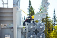
Figure 4 – Checking transformer fans and radiators

b) Expansion System and Conservator Tank
To accommodate oil expansion, transformers use:
- Conservator tanks: External tanks that store excess oil as temperature changes.
- Sealed tanks with nitrogen gas cushioning: Used in hermetically sealed transformers to maintain constant pressure.
1.6 Sealing and Leak Prevention in Transformer Tanks
Transformer tanks must be completely sealed to prevent oil leaks and moisture ingress, which can degrade insulation.
a) Types of Sealing Systems
- Welded seams: Ensure a permanent, leak-proof structure.
- Bolted gaskets (for modular tanks): Require high-quality oil-resistant gaskets to prevent leakage.
- Sealed bushings and valve connections: Prevent oil leakage at entry/exit points.
b) Moisture Protection and Breather Systems
- Silica gel breathers are used in conservator-type transformers to remove moisture from incoming air.
- Hermetically sealed transformers eliminate the risk of oil contamination by removing air exchange entirely.
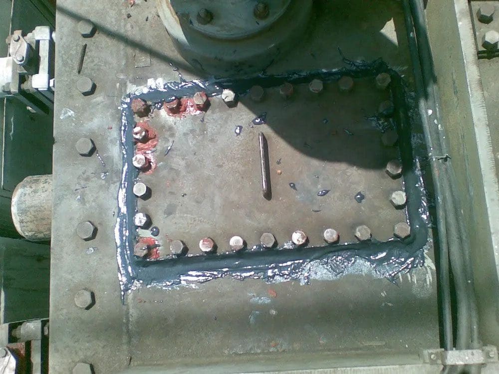
Figure 5 – Transformer tank oil leakage repair
1.7 Protection and Monitoring Devices on Transformer Tanks
Transformer tanks are equipped with protective and monitoring devices to detect faults and ensure safe operation.
- Buchholz Relay: Detects internal faults and gas accumulation in oil-immersed transformers.
- Pressure Relief Valve (PRV): Releases excess pressure in case of oil expansion beyond safe limits.
- Oil Level Indicator: Ensures proper oil levels are maintained.
- Thermal Sensors and RTDs: Monitor winding and oil temperature.
1.8 Transport and Handling Considerations
Transformer tanks must be designed for safe transport and installation, especially for large power transformers.
a) Transport Design Considerations
- Lifting lugs and jacking pads are provided for lifting and positioning.
- Base rails or skid mounts allow easy movement.
- Shock and vibration resistance is ensured by reinforcing the tank’s structure.
b) On-Site Installation and Maintenance
- Large transformers may be transported without oil, requiring proper sealing to prevent contamination.
- Modular tanks allow easy disassembly and reassembly for on-site installation.
Figure 6 – Transportation of a power transformer

2. Bushings and Terminal Connections in Power Transformers
In power transformers, bushings serve as insulated passageways for electrical conductors, allowing high-voltage connections to pass through the transformer tank while maintaining electrical isolation. Without properly rated bushings, internal insulation integrity could be compromised, leading to partial discharges, insulation breakdown, and system failures.
Terminal connections, on the other hand, are responsible for ensuring a secure, low-resistance electrical interface between the transformer and the connected power system.
To function effectively, bushings and terminal connections must:
- Provide electrical insulation between live conductors and the grounded transformer tank.
- Maintain mechanical and electrical stability under system operating conditions, including load fluctuations and short-circuit events.
- Withstand environmental stress, including moisture, pollution, and extreme temperatures.
- Minimize dielectric losses and prevent corona discharge, ensuring high insulation reliability.
- Prevent oil or gas leakage, maintaining the dielectric strength of oil-filled transformers.
2.1 Types of Transformer Bushings
Transformer bushings are categorized based on insulation material, operating voltage level, and application type. IEC 60137 classifies bushings into several types, each offering different advantages and considerations based on their dielectric properties and environmental resilience.
2.1.1 Oil-Impregnated Paper (OIP) Bushings
OIP bushings are the most widely used insulation type in high-voltage power transformers (above 66 kV). They consist of paper insulation impregnated with insulating oil, encased in a porcelain or composite outer shell.
However, they require regular monitoring for oil leakage and moisture ingress, which could degrade insulation performance.
Related electrical guides & articles


Muhammad Kashif
Muhammad Kashif Shamshad is an Electrical Engineer and has more than 17 years of experience in operation & maintenance, erection, testing project management, consultancy, supervision, and commissioning of Power Plant, GIS, and AIS high voltage substations ranging up to 500 kV HVAC & ±660kV HVDC more than ten years experience is with Siemens Saudi Arabia.Profile: Muhammad Kashif
