
Types of Generating Plants
Power generating plants are always a capital investment in all countries across the world. Not many countries are building new generating plants nowadays. As we all feel, a worldwide energy crisis of unparalleled severity and complexity is currently underway. The cliché “the poorest and most vulnerable will suffer most” will not be entirely true this time because energy production soon won’t be a matter of global, but instead of local character.
 Which types of power generating plants are worth planning and constructing nowadays?
Saying this, it’s a good idea for each country to think wisely and carefully plan their existing and future energy potentials.
Some of the standard ways for producing electrical energy include the combustion of fuel, while others use the utilization of renewable natural resources, such as wind, sun, water, and geothermal sources. These methods are all examples of conventional methods. It is not always the case that the natural resources are located in close proximity to the centers of load.
The majority of the time, renewable resources are situated in a location that is remote from the load, and the power that is generated is sent to the load centers through the use of lengthy transmission lines. The generating plants that use fuel, on the other hand, are constructed in closer proximity to the load centers, and the fuel resources are brought to the plants.
For the purpose of this discussion, let us talk about the most important facts about the primary sources of power generation and their characteristics.
- Solar Power Plant (Photovoltaic Plant)
- Concentrated Solar Plant (CSP)
- Wind Farm
- Hydropower Plant
- Diesel Engine Plant
- Gas Turbine Plant (Combustion Engine Plant)
- Thermal Power Plant (TPP)
- Nuclear Power Plant (NPP)
- Typical Capacity Factors for Power Plants
- Conclusion
- Typical Power Plant Single-Line Diagrams
- BONUS! Download Eight Guides Related to Power Generating Plants (PDFs, 63.7 MB)
1. Solar Power Plant (Photovoltaic Plant)
There is no more straightforward method of producing electricity than the solar power plant. There are a significant number of photovoltaic (PV) panels that are arranged on a level surface and oriented in the direction of the sun. In order to generate energy, the plates are able to absorb the sun’s rays. To generate the appropriate voltage, the plates are connected in such a way that they produce it.
This voltage is then transformed from direct current to alternating current in power inverters, and it is then lead to transformers, which convert it to a higher voltage and transfer it to the users who are located at a distance from the PV farm.
Sun trackers are utilized to follow the sun from sunrise to sunset in order to increase the amount of output of the system. Already constructed are plants with an installed capacity of one thousand megawatts.
The photochemical conversion efficiency of a panel typically ranges from 15% to 20%, depending on factors such as temperature, angle tracking, and time of day.
Solar power plants consist of the following fundamental components:
- Arrays of photovoltaic (PV) panels, either mounted in a stationary position or positioned on solar trackers. The prevailing panel utilized for these plants has a peak power rating of 200 W, which signifies its maximum output when subjected to direct sun radiation.
- Installation of wiring for collecting direct current (DC) electricity.
- Inverters to transform direct current (DC) into alternating current (AC) power.
- Transformers to step up or step down the voltage for distribution purposes.
- Data acquisition for the purpose of monitoring plant conditions.
- Addition of reactive power.
- Distribution lines and circuits to transmit electricity to a grid or individual users.
Figure 1 – Solar power plant (photovoltaic plant)

When the temperature is lower, panels convert more effectively. Any decrease in temperature of 10 degrees Celsius on the module results in a 4.5% improvement in the working behavior of the photovoltaic cells. At 85 degrees Celsius (185 degrees Fahrenheit), the cells lose their ability to focus. In a solar power plant, it is anticipated that the capacity factor will be somewhere in the range of thirty percent of the panel nameplate installed capacity.
Given that there is no solar input during the night hours, this presupposes that there is a variance in the solar input during the daylight hours.
The good things: Relatively cheap production and simple to maintain.
The bad things: High capital cost per kilowatt-hour produced, the need for a vast area, being located far from load centers, unpredictable power supply, a poor capacity factor, operating only during daylight hours, significant output losses, inability to provide reactive power, and challenges related to wind conditions.
2. Concentrated Solar Plant (CSP)
A concentrated solar power plant utilizes mirrors to focus solar energy in order to heat water or oil for running a thermal cycle involving low-pressure turbines and condensers. Plants use parabolic mirrors, Fresnel mirrors, and power tower technologies to focus the sun’s heat. Sun trackers are used to track the sun’s movement from sunrise to dusk.
Concentrated solar power planthas the capability to produce both thermal energy and electrical power. Heat can serve as a direct energy source for many thermal processes such as desalination and process heat. Electricity can power reverse osmosis systems and pump water from deep-water wells.
Concentrated solar plant technology is very adaptable and continuously developing.
Figure 2 – Concentrated solar plant: Reflective surfaces focus sunlight onto a heat exchanger positioned at a central tower

The power tower system has a central tower receiver that gathers concentrated solar radiation from a group of adjustable heliostats positioned on the ground, primarily on the north side of the tower in the Northern Hemisphere, enabling the heliostats to face south. Photovoltaic panels are not utilized. Solar mirrors are strategically positioned in various locations.
The operation of the tower relies on three primary components: heliostats, receptor, and tower. Heliostats are structures that consist of many mirrors fixed on individual posts. The heliostats need to have dual-axis three-dimensional trackers to maintain precise focus throughout the entire day.
The centralized receiver transmits solar radiation energy to a heat transfer fluid (HTF), which is then utilized to operate a traditional power cycle.
Figure 3 – Parabolic mirrors of a concentrated solar plant

The heating media has a potential temperature exceeding 600–700 °C, making it suited for smaller plants due to challenges in focusing from widely scattered heliostats during windy circumstances.
If the wind conditions are suitable, a tower plant has the potential to generate the highest temperature heating medium due to the short pipe system located only within the tower and separate heliostats.
The good things: Produced more cost-effectively and efficiently than photovoltaic installations. It has the ability to generate reactive power.
The bad things: It has a high capital cost per kWh, it is located in a remote location from load centers, it has environmental difficulties on power tower plants, it is impossible to estimate the supply of power, it has a poor capacity factor, it only runs during the day, it has significant output losses, and it has problems with wind.
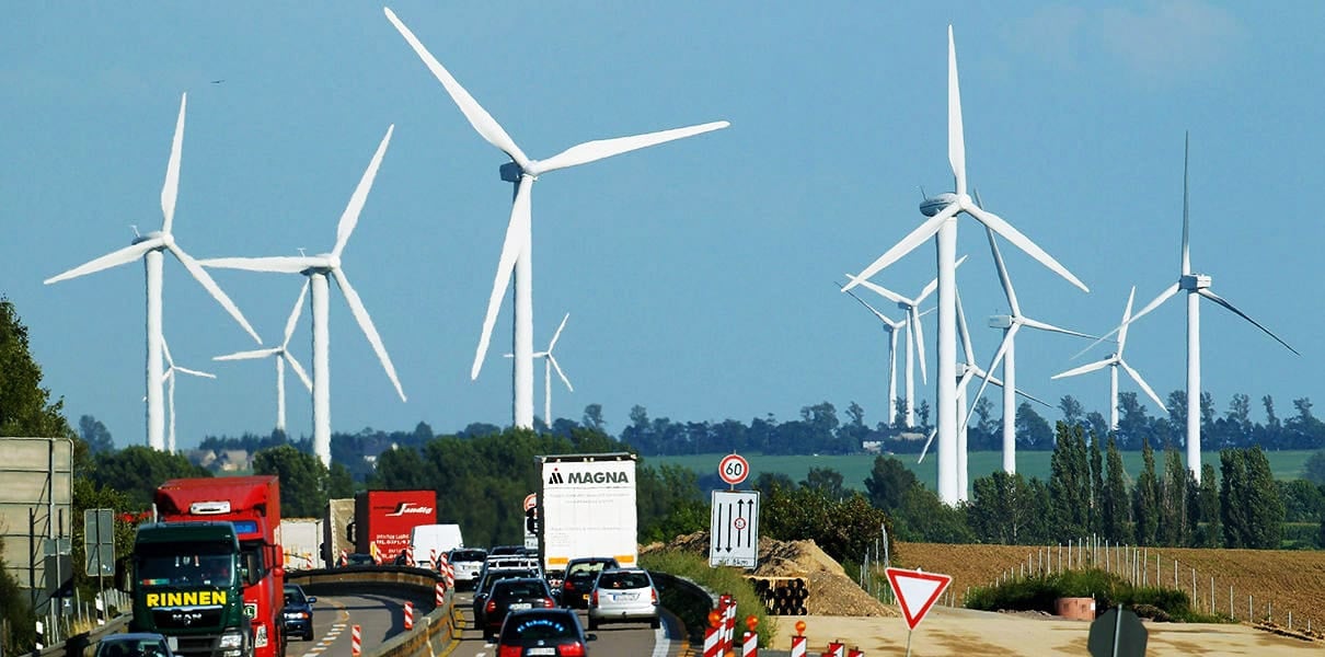
3. Wind Farm
The wind farm utilizes wind turbines that range from 1 to 7 megawatts. The design of the generator makes use of a wound rotor asynchronous generator model. This model obtains its excitation from the grid by means of AC/DC to DC/AC converters. This is for the reason that the wind is unpredictable.
The unit transformers are connected in a chain at a voltage of 33 kilovolts, and they are led to the main substation so that they can be connected to huge transformers that are responsible for transmitting power to far load centers.
Wind power typically costs between 0.04 and 0.06 US$/kWh, with a capacity factor (CF) of 30%. Wind power is cost-competitive on a per kWh basis, but developers face financial challenges because to its high initial investment costs. Wind farm sites located far from urban areas require the installation of transmission lines to transport electricity to cities, increasing development and construction expenses.
Due to the fact that the majority of wind farms are constructed on private land, the developer and landowner must reach a leasing agreement prior to commencing construction. Subsequently, the developer enters into an agreement with a local utility to sell the generated electricity and engages an engineering/construction firm to construct the facility.
After construction, the wind farm is frequently sold to an independent operator. Utilities frequently own and manage wind farms.
Figure 4 – Wind farm
The good things: Low cost production.
The bad things: Requires large area, power not predictable, used only when wind available, Difficult transport of blades. High installed capital cost per kWh. Remote from load centers. Low capacity factor. Large output losses. Wind turbulence issues. Requires import of reactive power at the main and unit stations.
Further Study – The art of the switchyard design: Case study of a 220/33 kV 200 MW wind farm
The art of the switchyard design: Case study of a 220/33 kV 200 MW wind farm
4. Hydropower Plant (HPP)
Hydropower generating stations are plants that generate electricity by utilizing water to drive the turbines and generators. These plants are also known as hydroelectric power plants. There is a wide range of plants that are utilized, including reservoirs and dams, run-of-river storage, and pumping storage. Each and every one of the plants is driven by the kinetic energy that is generated by the water as it travels downstream.
The power output of the plant is determined by the interaction between the water head (height) and the water flow.
P = 9.81 × W Q H 𝜂 × 10−3 kW
Where:
- P is the power, W – specific weight of water in kg/m3,
- Q is the rate of flow in m3/s,
- H is the height of fall (head) in meters,
- 𝜂 is the overall efficiency of operation.
For sites with low head and high volume, the plants use Kaplan turbines; Francis turbines are used for sites with 10–600 m head and 10–10 m3 of middle range volume; and Pelton turbines are used for sites with high head and low volume.
Constructing hydroelectric power facilities with a capacity factor of one hundred percent is a rare occurrence. It is very uncommon for a hydro project to operate at a capacity factor of fifty percent, yet there were hydro plants being constructed with a projected annual capacity factor of twelve percent.
Figure 5 – Hydropower plant (HPP)

In other words, a plant that has an installed capacity of 100 megawatts and a predicted capacity factor of 12 percent is only capable of producing 12 megawatts on a daily average during the entire year, based on the estimated amount of water that is available. The production of power occurs when there is sufficient water to bring it down to the minimal level required for operation.
Producing power below the minimum operating level would be an extremely inefficient use of water resources, and it could be difficult to recover back to the higher, more efficient operating levels if it were to occur.
These plants, which have low capacity factors, may be used for base load generation during the rainy seasons. Additionally, they may be used as peaking plants due to their ability to start up quickly, which is advantageous during times when the marginal energy cost is at its highest.
The good things: Production that is low in cost, capable of being utilized as base or peaking power, and able to start up quickly within one minute. Adaptable to fluctuating demand, the resource can also be utilized as a spinning reserve, it can be built to function as a synchronous condenser to supply MVARs, it is easy to operate and maintain, and it has an efficiency of 80–85%.
The bad things: The capacity factor can range anywhere from 15 to 50 percent, and the amount of water that flows into the dam is unpredictable from year to year. The capital expenditure for the civil works that create the catchment and the main dam is substantial.
Suggested Guide (PDF) – Design of 33kV switchyard (equipment, SLD, and layout) for small hydro-power plant
Design of 33kV switchyard (equipment, SLD, and layout) for small hydro-power plant
5. Diesel Engine Plant
Diesel engine plants utilize liquid or gaseous fuel combined with ambient air as the operating fluid. During the suction stroke, the gasoline undergoes compression and ignition within the cylinders. Thermal energy is transformed into mechanical energy to drive the pistons and rotate the electric generator.
Diesel engine plants are constructed for isolated settlements and maritime vessels. The plants typically function as continuous base load generation, operating 24 hours a day to provide power to industrial facilities and residential areas. The base load engines are slow-speed 400–900 rpm engines designed for continuous operation.
High and low-grade waste heat can be used for winter heating and industrial purposes, increasing plant efficiency from 40% to 80%.
Units operating at a moderate speed use around 0.225 kg of fuel per kilowatt-hour generated. Engines with a lower base load require around 0.192 kilograms of fuel per kilowatt-hour generated. Recovering waste heat from the engine to use for plant processes and room heating can increase fuel efficiency from 40% to over 80%. Diesel engines operate most efficiently when they are loaded to 85% or more of their capacity.
Extended operation of engines at reduced power levels decreases efficiency and increases susceptibility to clogging and malfunction.
Figure 6 – Diesel engine power plant

Diesel gensets usually operate at 42% efficiency while running at full load and at 37% efficiency at 50% load, without taking into account the auxiliary plant load. During the winter months, the overall efficiency reaches approximately 80% due to the utilization of waste heat from the engines. During summer days, excess heat may need to be released into the sky.
The good things: Low initial investment, fast setup, excellent effectiveness, waste heat utilization, rapid activation, ideal for tiny isolated populations, and appropriate for peak demand.
The bad things: High fuel expenses, environmental pollution concerns, and loud.
Good Reading – The essentials of standby power systems you SHOULD install before the blackout happens
The essentials of standby power systems you SHOULD install before the blackout happens
6. Gas Turbine Plant (Combustion Engine Plant)
The gas turbine plant is equipped with a combustion engine that is capable of converting either gaseous or liquid fuels into mechanical energy. 80 percent of natural gas is composed of methane. The gas turbine engine is responsible for compressing air and combining it with fuel, which is then burned at high temperatures. This process results in the production of a hot gas that serves to turn a generator and make the turbine blades spin while simultaneously exhausting gas into the atmosphere.
The energy that is generated by burning is transformed into electricity. 30 percent is the expected level of efficiency.
Plants are constructed with numerous turbine units, each of which has a capacity of 10–250 megawatts (MW). Additionally, there is the option of including combined cycle thermal generating on each pair of turbine units by utilizing the exhaust gas temperature reaching 540 degrees Celsius.
The combustion turbine experiences a deterioration factor of around 3.5% every 1000 ft rise in elevation, whereas the ambient temperature degrades at a similar rate each 10° increase.
Figure 7 – Gas-turbine power plant

The good things: Low capital cost, quick plant construction, waste heat recovery possibility, quick engine start for peaking duty, and suitable for small remote communities.
The bad things: High fuel cost and environmental emissions issues.
7. Thermal Power Plant (TPP)
A thermal power plant is a type of power plant that is powered by fossil fuels. It employs the combustion of coal, natural gas, waste, or petroleum to generate steam at high pressure and temperature in a boiler. This steam is then used to drive steam turbines, which in turn drive electrical generators. In order to ensure continuous operation and base loading, thermal power plants are designed to be constructed on a massive scale.
Approximately one or two 400–600 MW units are utilized by the majority of the plants.
Large amounts of infrastructure are required for the handling and storage of coal in coal-fired plants. The Environmental Protection Agency (EPA) mandates that exhaust scrubbers be installed in order to control pollution. When it comes to controlling gaseous emissions, particularly acid gasses, scrubbers are among the most important controlling equipment. Furthermore, the pollution control contributes to the station load, which in turn results in a significant decrease in the plant’s efficiency.
Thermal energy is the primary and most dependable form of electricity production in numerous countries globally. In India, for example, about 60% of electric power is generated by steam plants. India possesses a substantial coal reserve of over 170 billion tonnes, ranking it as the fifth largest in the world.
Steam power plants can be placed to produce electricity alone or to provide electricity as well as steam for various industrial applications such paper mills, textile mills, sugar mills, refineries, chemical industries, plastic manufacturing, and food manufacturing.
Steam is collected from a specific area of the turbine for process purposes, while the rest of the steam is let to expand within the turbine. Alternatively, the steam released from the exhaust might be utilized for industrial processes. Thermal stations can be either private industrial units or central stations.
Figure 8 – Thermal power plant
The power plant should be located in close proximity to the load center to minimize transmission costs and losses. This component is crucial when a DC supply system is utilized. AC power systems allow for energy translation between different voltage levels, enabling power plants to be located farther from the load if favorable conditions exist.
It takes a significant quantity of coal to generate the steam that is needed. Considering that the government’s objective is to only employ low-grade coal that contains between 30 and 40 percent ash for the purpose of power generation, steam power stations ought to be situated in close proximity to coal mines in order to prevent the transportation of coal and ash around the country.
The good things: Base load operation, low capital cost per kWh, high capacity factor: from 60 to 70%.
The bad things: Pollution control, slow to start, and high standby operational losses.
Suggested Reading – 12 essential parameters required for rating large generators
12 essential parameters required for rating large generators
8. Nuclear Power Plant (NPP)
A nuclear power plant is a thermal power station that utilizes uranium as fuel for a chain fission reaction. The nuclear reactor functions as the primary heat source for the power plant. Fuel is inserted into the reactor core, where controlled nuclear fission occurs, generating heat through moderation. Throughout a standard thermal cycle, heat is transferred through a heat exchanger, leading to the creation of pressurized steam and the generation of electricity.
Plain water Water, carbon in solid form, or deuterium oxide There are three sorts of chemicals, including heavy water D2O, that can moderate the nuclear chain reaction in the reactor core, depending on the specific reactor type. The extremely radioactive spent fuel taken out of the reactor is stored in water basins at the site and was removed from the reactor.
A new nuclear power station incurs significantly greater initial capital expenses compared to rival technologies, resulting in a higher overall generation cost for new nuclear power in comparison to alternatives like coal and natural gas.
Figure 9 – Nuclear power plant

8.1 Costs of New Nuclear Power Plant
To fully understand the economics of nuclear power, it is crucial to grasp its cost elements and the factors that influence them. Nuclear power generation expenses can be divided into three main categories: capital costs, finance costs, and operating costs.
Capital costs are the primary expense in nuclear power generation and are usually expressed as overnight costs, which do not include financing expenses. Capital costs consist of many expenses, such as engineering-procurement-construction costs, which encompass the expenses associated with constructing the plant, including physical plant equipment, materials, and labor. This is the typical cost estimate provided by the reactor’s supplier.
Vendors add contingency costs to account for unforeseen expenses. These expenses can be discussed and governments may agree to cover them.
Figure 10 – Refuel pool for reactor

8.2 Economic Competitiveness
When evaluating economic competitiveness, it is important to differentiate between current nuclear power plants and newly constructed nuclear power plants. Old nuclear power stations are cost competitive due to the significant recovery of their capital expenditures. Nuclear units have lower variable costs, like as fuel and O&M, in comparison to fossil-fueled generators.
However, new nuclear power facilities are economically uncompetitive because of their large initial costs.
Currently the economic viability is affected by:
- High capital costs;
- Lengthy construction periods, because of interruptions by engineering and management problems, regulatory delays and public opposition;
- Market deregulation;
- Extended period of time without nuclear power plant constructions; and
- Relatively inexpensive electricity generated from other fuel sources.
The duration of the building phase significantly influences the competitiveness of nuclear power due to its effect on financing expenses. Interest on the borrowed funds is accumulating while the factory is being constructed. Increased construction time and interruptions result in higher interest costs that must be repaid when the plant begins producing power.
To enhance the competitiveness of nuclear power, new nuclear facilities must be constructed with more stringent timelines.
The good things: Low production cost, base load operation, and no pollution or CO2.
The bad things: Long planning and regulation process, high construction cost, radioactivity, fuel and core containment requirements, spent fuel storage.
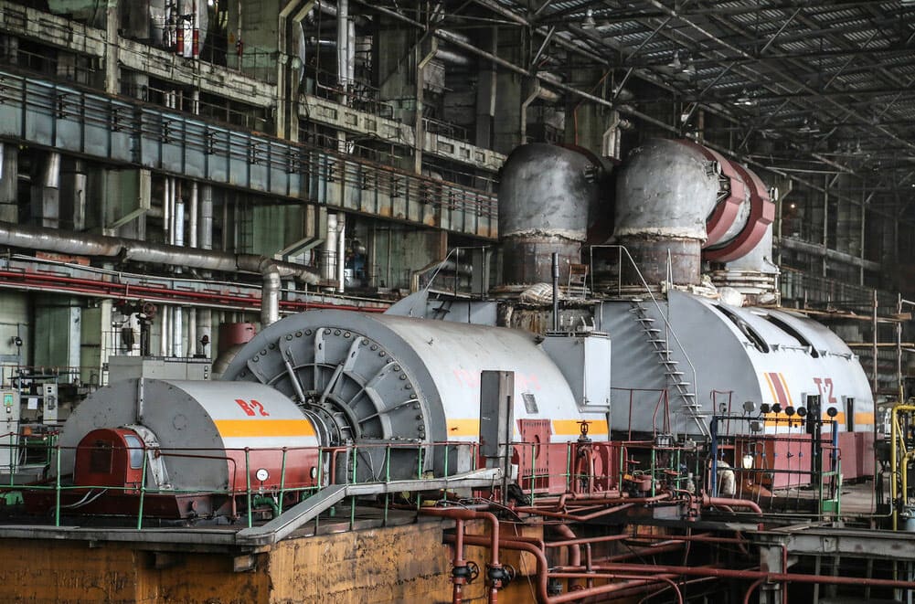
Figure 11 – Heat exchange mechanism and the electricity generator in a nuclear power plant

9. Typical Capacity Factors for Power Plants
1. Thermal power plant
Expected capacity factor is 60–65% It’s a base load generation.
Thermal power plant capacity 4000 MW (4×1000 MW Units) produces annual energy of 21 725 000 MWh.
Calculate annual plant capacity factor CFa × 365 days × 24 h = 8760 h/yr.
The capacity factor is dependent on the daily load cycle, as well as scheduled and forced outages at the facility.

2. Hydroelectric power plant
Expected capacity factor: 38–50%. It’s a peaking power nature.
Nameplate capacity: 200 MW (4×50 MW Units). Annual energy production: 700 800 MWh.
The capacity factor relies on the seasonal availability of water. The plant produces electricity at a high rate during wet seasons to prevent water overflow and at a reduced rate during dry periods.
It’s commonly utilized as spinning reserve to steady the system because of its quick start capability. Planned outages can be arranged to coincide with yearly dry seasons.

3. Nuclear Power Plant
Capacity factor expected: 80–93%. It’s a base load generation.
Plant nameplate capacity: 2400 MW (4 × 600 MW), Annual energy production: 16 800 000 MWh
The capacity factor depends on the daily load cycle and planned and forced outages of the facility.

4. Solar (Photovoltaic) Plant
Capacity factor range expected: 13–19%. Solar dependable.
Nameplate capacity: 3 MW, Annual energy production: 450 000 MWh.
The capacity factor depends on the plant’s location and periods of high insolation. Power storage capacity is restricted.

5. Concentrated Solar Plant (CSP)
Capacity factor range expected: 25–35%. It’s a tube and tower type.
Plant nameplate capacity: 350 MW, Annual energy production: 9 100 000 MWh

6. Wind Power Farm
Capacity factor range expected: 20–40%.
Wind farm capacity: 80 MW (40×2 MW), Annual energy production: 180 600 MWh.
Capacity factor for wind energy is dependable and varies seasonally. Strong winds and weak winds are not beneficial.

10. Concusion
We covered the fundamental aspects of each category of power plants and the anticipated ranges of their capacity factors. We presented some empirical data that can provide valuable insights.
It is crucial to highlight that thermal and nuclear power plants are the most reliable and expensive producing facilities to develop. Both options entail significant initial investment, operate at high efficiency levels, and experience substantial standby operational inefficiencies. Conversely, operational costs are quite low compared to other types of plants.
Diesel engine plants provide a specific role in the power system in rural areas, but they are not the primary power source.
Each type of generating plant has unique requirements related to terrain, access to water, closeness to electrical transmission lines, and availability of necessary resources for operation.
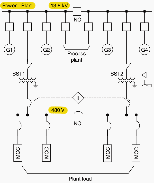
11. Power Plant Single-Line Diagrams
Figures 12 and 13 illustrate two distinct forms of single-line diagrams for power plants, each of which contains two producing units. The first one is utilized for smaller plants that have generating units that are up to sixty megawatts (MW), while the second one is implemented for systems that have larger generating units.
The location of the generator circuit breaker (GCB) is the primary distinction between the two installations.
As a result of their proximity to the generators, the generator control boards (GCBs) are costly pieces of machinery that take up a significant amount of space on the floor of the generators.
Both single-line diagrams contain producing units, GSUT, Generator step-up transformer; UAT, unit auxiliary transformer; SST, station service transformer; GCB, and generator circuit breaker.
Figure 12 – Power plant with smaller units
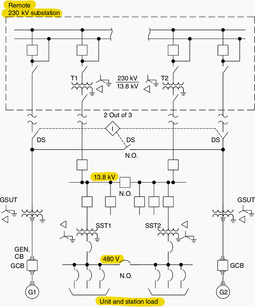
Figure 13 – Power plant, larger units
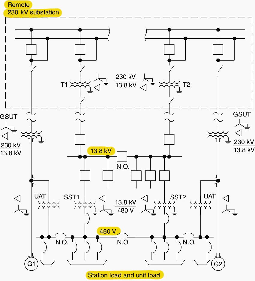
The other approach used for larger generator currents is not to have a GCB, but connect the generators directly to the output transformers within the plant and connect the transformers at HV to the remote switchyard. In this case, the generator synchronizing and switching is done by remote switchyard breakers.
A plant single-line diagram for a diesel generating plant is completely different and shown in Figure 14.
Figure 14 – Diesel generator plant basic single-line diagram
12. BONUS! Eight Guides Related to Power Generating Plants (PDFs)
Download BONUS: Eight guides related to power generating plants (PDF) (for premium members only):
Resources:
- Practical Power Plant Engineering by Z. Bedalov
- Hydropower in Norway by Arne Kjølle (Professor Emeritus Norwegian University of Science and Technology)
- Power Plant Design by Khalil, E.E.
- Complete Guide To Photovoltaic Plants by ABB
Related electrical guides & articles


Edvard Csanyi
Hi, I'm an electrical engineer, programmer and founder of EEP - Electrical Engineering Portal. I worked twelve years at Schneider Electric in the position of technical support for low- and medium-voltage projects and the design of busbar trunking systems.I'm highly specialized in the design of LV/MV switchgear and low-voltage, high-power busbar trunking (<6300A) in substations, commercial buildings and industry facilities. I'm also a professional in AutoCAD programming.
Profile: Edvard Csanyi

Can you verify the amp Eric value of the 3MW solar PV generation in captivity factor calculation.